
Running GoLang on an STM32 MCU. A quick tutorial.
If you’re a fan of GoLang then your options are limited in the embedded world. So, here’s a couple of options for you with a working bare metal example for an STM32 MCU written entirely in Go.
What is GoLang?
GoLang all started back in 2009 by a bunch of Google employees; Robert Griesemer, Rob Pike & Ken Thompson., (yes the Ken Thompson who worked with Dennis Ritchie on the original UNIX O/S).
According to Google:
Pros & cons
I was originally going to provide more details about GoLang here, but the best place to learn about Go is on the GoLang Tour website.
If you really want me to go into GoLang more, then leave a comment below.
Also check out this article from a talk back in 2012 on why GoLang appeared in the first place.
Frameworks vs bare metal
Currently we have two options for Go in the embedded world. Either using a GoLang based framework or bare metal programming of a device.
GoLang Frameworks
For frameworks there’s embd and gobot.
embd
embd is something that hasn’t seen much work done on it in the last year. It’s an almost complete framework supporting only a handful of SBCs.
So, it isn’t the best one out there.
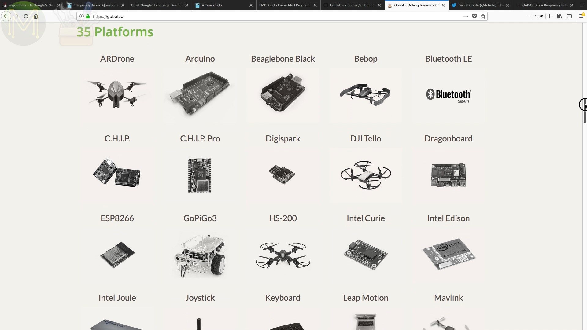
gobot
The best GoLang based framework for IoT is gobot.
There’s a couple of good examples of what you can do with it.
One of my Patrons, Daniel Chote, is creating a 3D printable robotic lawn-mower using OpenCV and 9DOF IMUs.There’s also GoPiGo from Dexter Industries which is a DIY robot built around GoLang and supported by gobot.gobot currently has support for 35 platforms ranging from BeagleBones, Raspberry Pis, OpenCV, down to ESP8266 and Arduinos.

The device support, such as sensors, isn’t as mature, but adding devices is pretty easy since the framework uses Go.
However, for MCU platforms such as the Arduino, you don’t write in Go for the MCU, but burn the firmata firmware to your device which can be accessed from your Go code running on, for example, a Raspberry Pi.
GoLang Bare Metal
If you really want to program in Go for your MCU, then the only other viable option is using emgo, written by Michal Derkacz.
This doesn’t compile Go code directly to assembler, but rather trans-piles, or converts, Go to C and then compiles that to assembler. While this seems to be a roundabout way of doing things, it actually makes it very clean.
You can write all your code in Go targeting an MCU and benefit from Go’s extensibility.
func init() {
    system.SetupPLL(8, 1, 72/8)
    rtcst.Setup(32768)

    // GPIO
    // SCLK - orange    - D13   - PA5
    // MISO - purple    - D12   - PA6
    // MOSI - blue      - D11   - PA7
    gpio.A.EnableClock(true)
    spiport, sck, miso, mosi := gpio.A, gpio.Pin5, gpio.Pin6, gpio.Pin7

    // CS   - green     - D10   - PA4
    // DC   - yellow    - D9    - PB7
    gpio.B.EnableClock(true)
    ilics := gpio.A.Pin(4)
    ilidc := gpio.B.Pin(7)
    ilireset := gpio.A.Pin(10)

    // SPI
    spiport.Setup(sck|mosi, &gpio.Config;{Mode: gpio.Alt, Speed: gpio.High})
    spiport.Setup(miso, &gpio.Config;{Mode: gpio.AltIn})
    d := dma.DMA1
    d.EnableClock(true)
    lcdspi = spi.NewDriver(spi.SPI1, d.Channel(3, 0), d.Channel(2, 0))
    rtos.IRQ(irq.SPI1).Enable()
    rtos.IRQ(irq.DMA1_Channel2).Enable()
    rtos.IRQ(irq.DMA1_Channel3).Enable()

    // Controll
    cfg := gpio.Config{Mode: gpio.Out, Speed: gpio.High}
    ilics.Setup(&cfg;)
    ilics.Set()
    ilidc.Setup(&cfg;)
    cfg.Speed = gpio.Low
    ilireset.Setup(&cfg;)
    delay.Millisec(1) // Reset pulse.
    ilireset.Set()
    delay.Millisec(5) // Wait for reset.
    ilics.Clear()

    lcd = ili9341.NewDisplay(ilidci.New(lcdspi, ilidc, 36e6), 240, 320)
    lcd.DCI().Setup()
}
So, adding support for new MCUs and devices is fairly easy.
However, there are a couple of downsides to using emgo. The best way to show you, is to run through a simple blinky LED example written in Go.
GoLang on an MCU - an example
Hardware
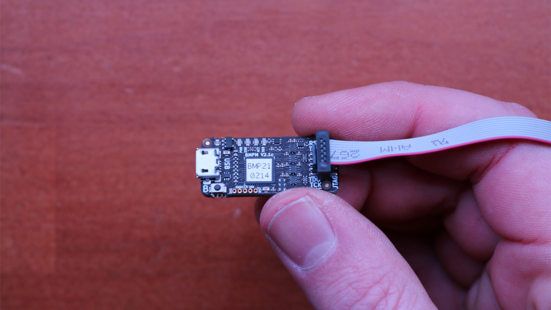
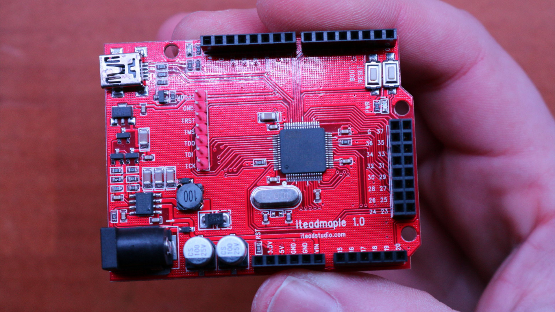
First of all you’ll need a programmer. I used an STlink v2 for this.Although you can also use a Black Magic Probe.I also used an STM32F103 based board from Itead, which is a Maple clone. You can use almost any STM32 based MCU as a lot of them are supported by emgo.For this, of course I’ll need the JTAG header soldered up and connected up to the STlink programmer.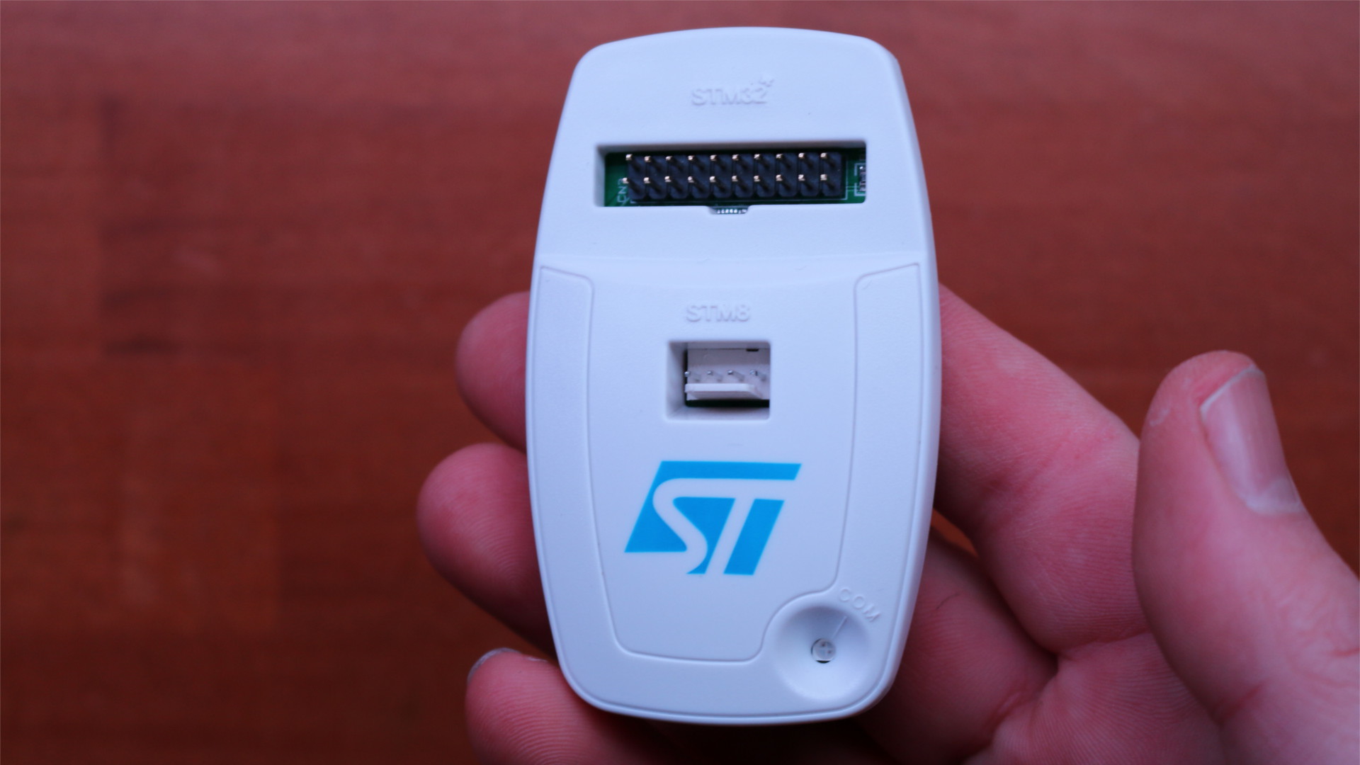
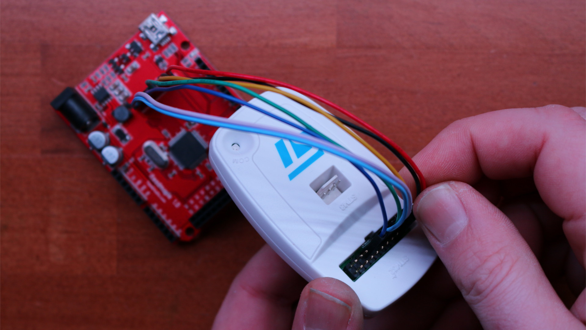
Apply juice to both the STlink and Maple clone and two LEDs should be enough for this.
Software
Now I’m assuming that you already have Linux installed and GoLang all setup. GoLang is available either from your O/S repo or from the GoLang website. Installing is fairly basic, so I’ll skip over that bit.
However, you should end up with a Go src directory. EG: ~/go/src
Next you’ll need to install emgo.
mkdir -p ~/go/src/github.com/ziutek
cd ~/go/src/github.com/ziutek
git clone https://github.com/ziutek/emgo.git
cd emgo/egc
go install
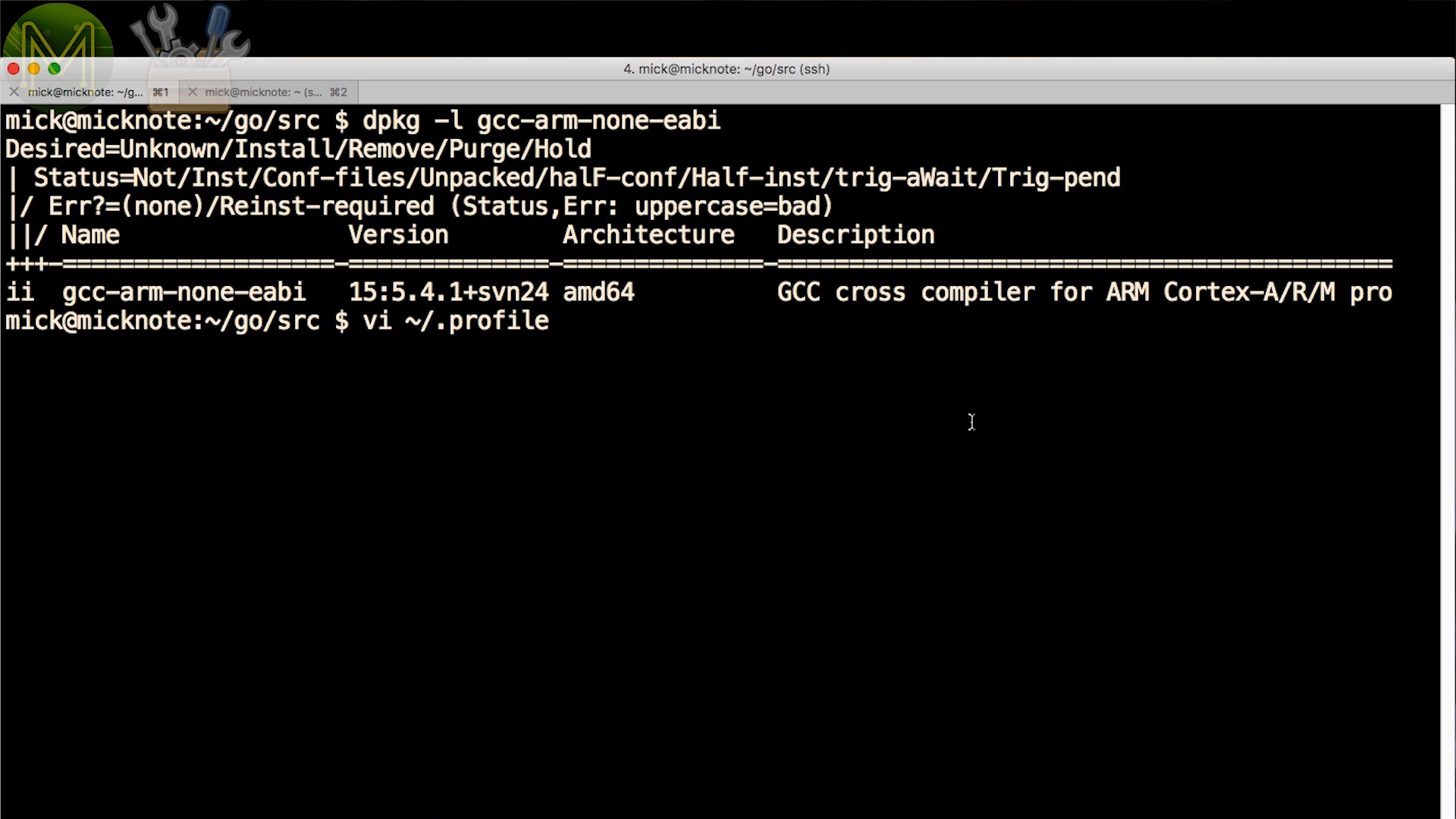
Then you’ll need to add in some environment variables to your shell profile.
PATH="$HOME/bin:$HOME/go/bin:$HOME/share/esp/xtensa-esp32-elf/bin::/usr/lib/go-1.10/bin:$PATH"

GOPATH="${HOME}/go:/usr/lib/go-1.10/src"; export GOPATH

EGCC=/usr/bin/arm-none-eabi-gcc; export EGCC
EGLD=/usr/bin/arm-none-eabi-ld; export EGLD
EGAR=/usr/bin/arm-none-eabi-ar; export EGAR

EGROOT=${HOME}/go/src/github.com/ziutek/emgo/egroot; export EGROOT
EGPATH=${HOME}/go/src/github.com/ziutek/emgo/egpath; export EGPATH

EGARCH=cortexm3; export EGARCH
EGOS=noos; export EGOS
EGTARGET=f10x_md; export EGTARGET
This references the GCC build chain binaries, a couple of other variables and two important variables that you need to match to your STM32 MCU.
EGARCH=cortexm3
EGTARGET=f10x_md
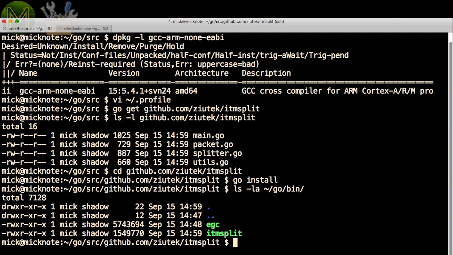
If you are using SWD instead of JTAG, then you can also fetch the itmsplit Go code, which allows you to see SWD debug messages.
go get github.com/ziutek/itmsplit
cd ~/go/src/github.com/ziutek/itmsplit
go install
Demo code
Next fetch the demo archive from GitHub. You should end up with a bunch of files like this.
-rwxr-xr-x 1 mick shadow 197 Sep 15 20:26 burn.sh
-rwxr-xr-x 1 mick shadow 120 Sep 15 20:16 debug-oocd.sh
-rw-r--r-- 1 mick shadow 500 Sep 16 13:21 main.go
-rw-r--r-- 1 mick shadow 15816 Jan 22 2016 maple_boot.bin
-rwxr-xr-x 1 mick shadow 166 Sep 16 12:12 revert-maple-bootloader.sh
-rw-r--r-- 1 mick shadow 280 Sep 16 10:45 script.ld
The script.ld file controls key elements of the resulting MCU firmware image.
ISRStack = 2048;
MainStack = 2048;
TaskStack = 2048;
MaxTasks = 1;

/* bootRAM code should by placed at 0x200001E0. */
/*bootOffset = 0x1E0;*/

INCLUDE stm32/f103rb
INCLUDE stm32/loadflash
INCLUDE noos-cortexm

/* Include bootRAM and set it as entry point. */
/*ENTRY(bootRAM)*/
You have stack size definitions and MaxTasks, which are one of the short-comings of emgo - you will have to define the number of tasks running and also stack sizes here.
There’s also several include files that need to match your target MCU.
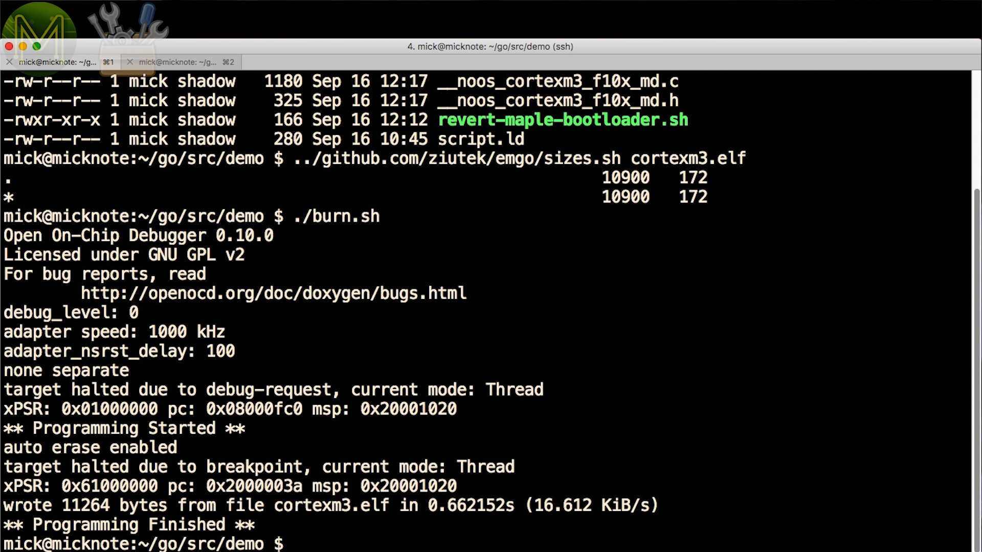
Next the burn.sh script will compile the demo Go code and burn it to the target device.
#!/bin/bash

rm cortexm3.elf __noos_cortexm3_f10x_md.c __noos_cortexm3_f10x_md.h
egc
openocd -d0 -f interface/stlink-v2.cfg -f target/stm32f1x.cfg -c 'init; program cortexm3.elf; reset run; exit'
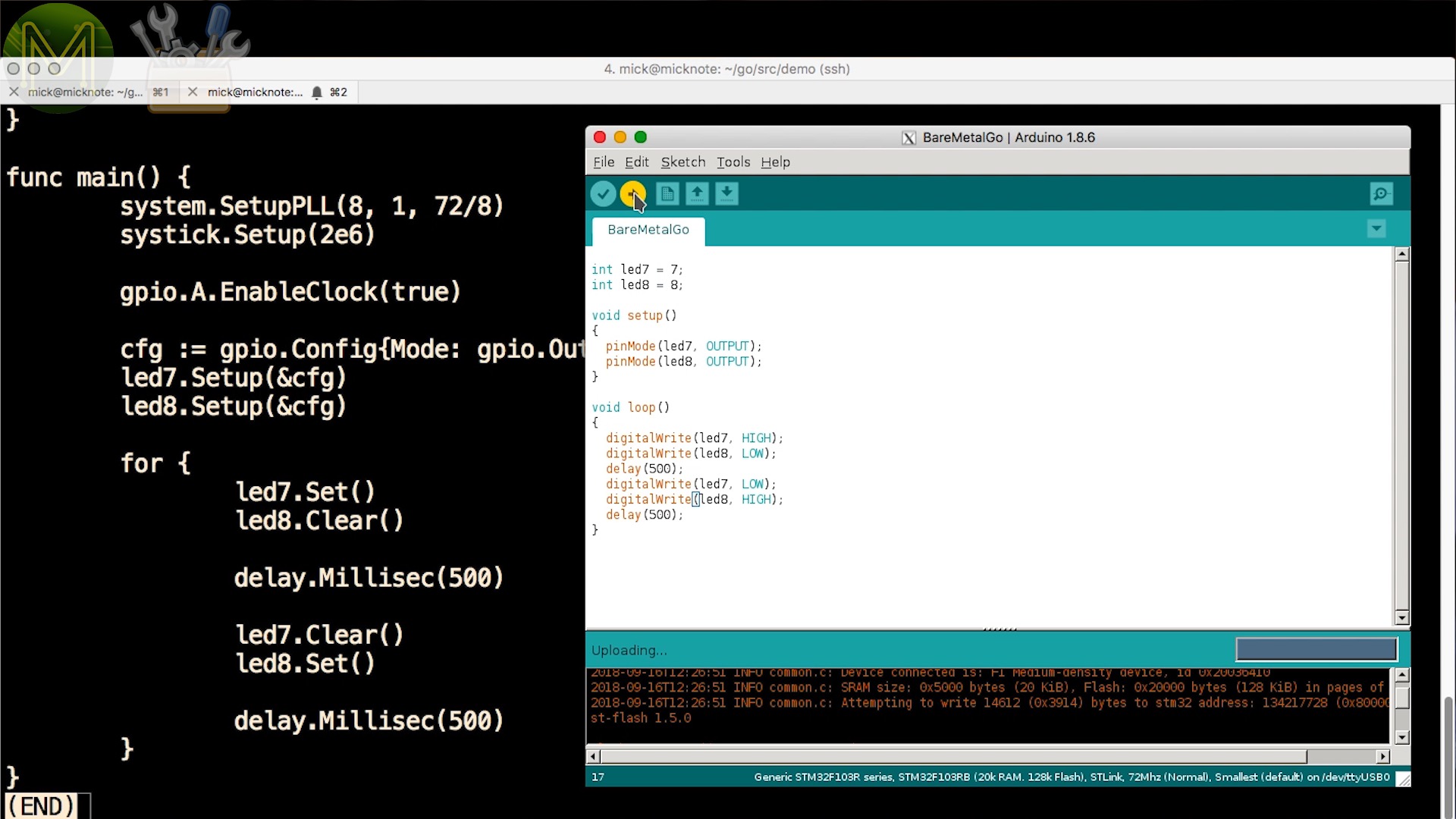
Then there’s main.go which contains a very simple LED flashy code.
package main

import (
    "delay"

    "stm32/hal/gpio"
    "stm32/hal/system"
    "stm32/hal/system/timer/systick"
)

var (
    led7 = gpio.A.Pin(7)
    led8 = gpio.A.Pin(6)
)

func init() {
}

func main() {
    system.SetupPLL(8, 1, 72/8)
    systick.Setup(2e6)

    gpio.A.EnableClock(true)
    gpio.B.EnableClock(true)

    cfg := gpio.Config{Mode: gpio.Out, Speed: gpio.Low}
    led7.Setup(&cfg;)
    led8.Setup(&cfg;)

    for {
        led7.Set()
        led8.Clear()

        delay.Millisec(500)

        led7.Clear()
        led8.Set()

        delay.Millisec(500)
    }
}
- Two LEDs are defined, GPIO 7 and 8 on Port A.
- Then the PLL is set to reference the internal 8MHz oscillator, with a PLL divider set to 1, with a system clock of 72MHz.
- And a systick wakeup timer set to 2mS.
- EnableClock enables the clock for GPIO port A.
- Then define a default GPIO configuration, which is an output and apply this config to the two LED pins.
- Then loop forever just toggling the pins, waiting for 500mS in-between.
Flashing the MCU
Running the egc binary you can see that small example taking up almost 11KB of flash. That’s actually a huge amount for just flashing two LEDs. The equivalent assembler can be written in a 100th of that, but remember we are coding up in Go designed to be able to run on high-end servers.So, now we can burn that straight to the Maple board.And there you go! Two flashing LEDs written entirely in GoLang!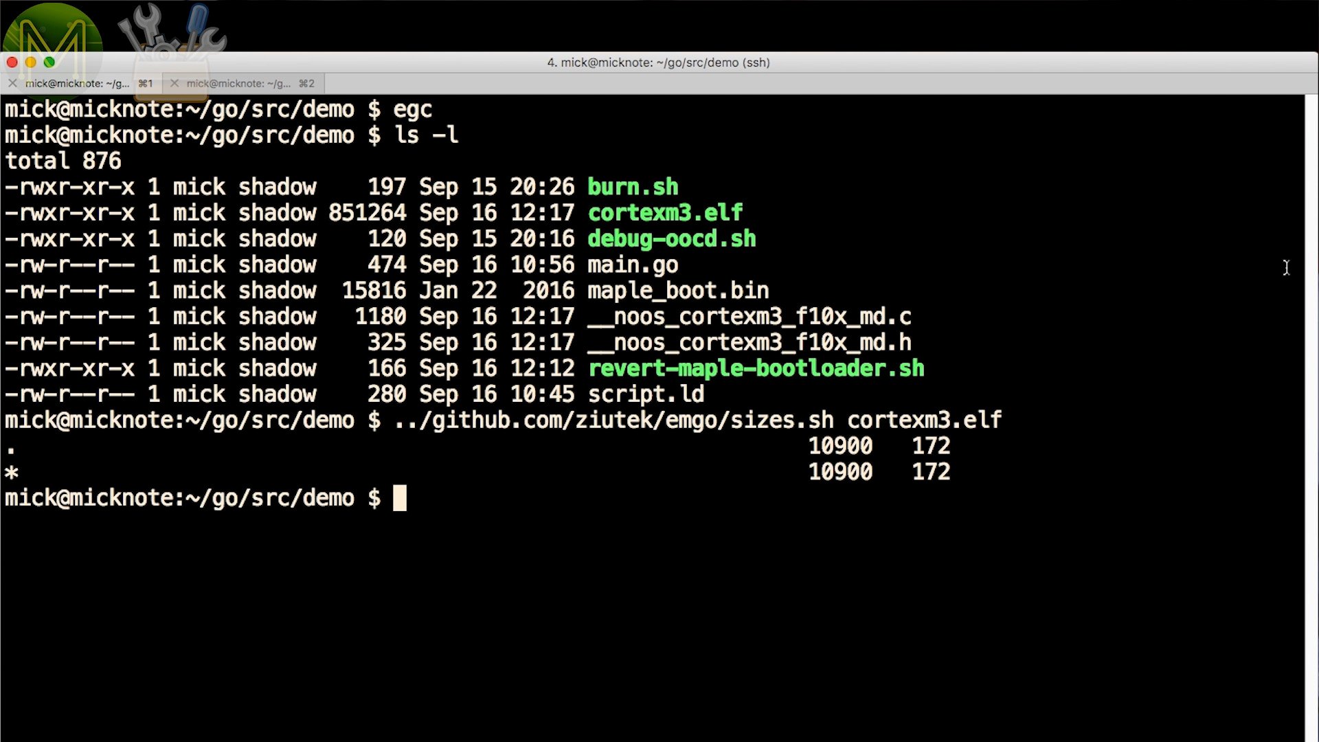

Under the hood
To see what emgo is doing under the hood, you can see the trans-piled output. Two files are generated. Even though it’s a little difficult to follow, it is quite human readable standard C, which is good.
#include "__noos_cortexm3_f10x_md.h"

// type decl
// var  decl
static stm32$hal$gpio$Pin main$led7;
static stm32$hal$gpio$Pin main$led8;
// func decl
// const decl
// type def
// var  def
static
__typeof__(main$led7) main$led7;
static
__typeof__(main$led8) main$led8;
// func def
static // 0
void main$0init() {
}
 // 29
void main$main() {
    stm32$hal$system$SetupPLL(8L, 1L, 9L);
    stm32$hal$system$timer$systick$Setup(2000000);
    stm32$hal$gpio$Port$EnableClock(stm32$hal$gpio$A, true);
    stm32$hal$gpio$Port$EnableClock(stm32$hal$gpio$B, true);
    stm32$hal$gpio$Config cfg$ = ((stm32$hal$gpio$Config){.Mode = 1, .Speed = 1});
    stm32$hal$gpio$Pin$Setup(main$led7, &cfg;$);
    stm32$hal$gpio$Pin$Setup(main$led8, &cfg;$);
    for (;;) {
        stm32$hal$gpio$Pin$Set(main$led7);
        stm32$hal$gpio$Pin$Clear(main$led8);
        delay$Millisec(500L);
        stm32$hal$gpio$Pin$Clear(main$led7);
        stm32$hal$gpio$Pin$Set(main$led8);
        delay$Millisec(500L);
    }
}
// init
void main$init() {
    stm32$hal$gpio$init();
    stm32$hal$system$init();
    stm32$hal$system$timer$systick$init();
    runtime$init();
    internal$init();
    delay$init();
    main$led7 = stm32$hal$gpio$Port$Pin(stm32$hal$gpio$A, 7L);
    main$led8 = stm32$hal$gpio$Port$Pin(stm32$hal$gpio$A, 6L);
    main$0init();
}
This is important when it comes to debugging as you’ll need to see exactly where you’re up to in your Go code.
Contained within the demo files on my website there’s also a boot-loader reverter script. So that you can go back to the default firmware if you need to.
#!/bin/bash

openocd -d0 -f interface/stlink-v2.cfg -f target/stm32f1x.cfg -c 'init; reset halt; flash write_image erase maple_boot.bin 0x08000000; reset run; exit'
As you can see, there’s slightly more setup code you have to apply in Go, but Michal has done a pretty good job of making it simple.
To be honest I much prefer the GoLang way.
Things that go Pffft
Now, I was going to show you how to connect up an AdaFruit ILI9341 LCD screen to the STM32 and display graphics using Go, but unfortunately I suspect I buggered my display and it wasn’t functioning, even with AdaFruit’s Arduino code.
So, that will be something for another video.
Summary
So, GoLang is a pretty versatile language and my money is on it gaining traction in the Maker scene as it’s a lot more extensible and predictable than other languages like Python.
However, it has a lot of catching up to do with languages like Rust for low end MCUs.
