SMS over LoRa: Long distance SMS without 4G // Project
Do you want to be able to send an SMS over 20kms without using a mobile phone network? Here’s one small project you can knock up in less than a day allowing you to send an SMS over LoRa.
LoRa
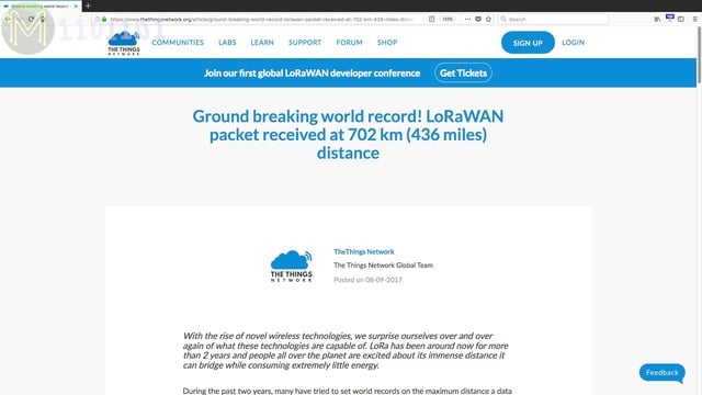
LoRa is a great technology allowing you to send messages over very long distances. We’ve seen several attempts reaching over 200kms, (Andreas Spiess), and even 700kms using low altitude balloons.
However, around the suburbs, with a decent antenna, you should be able to reach 20kms comfortably.How does it work?
So, how can you use LoRa to send messages long distances?
The idea is pretty basic.
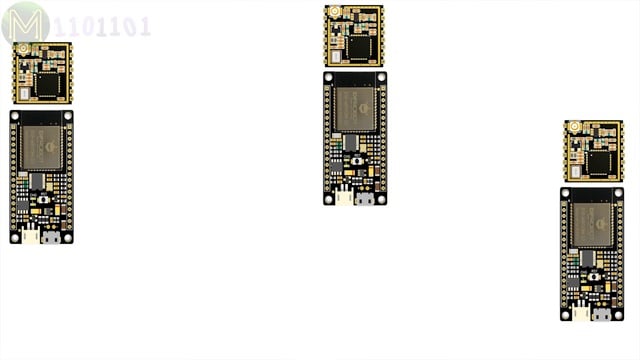
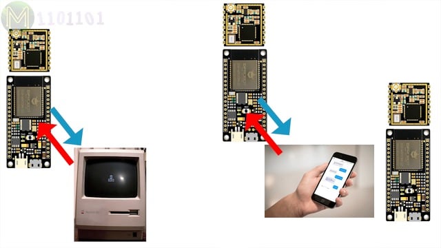
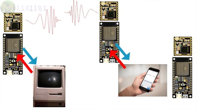
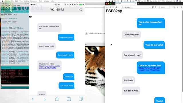
You have two or more devices with on-board ESP32 and LoRa module.Each of the ESP32s will create a WiFi Access Point. On your mobile phone or PC you join to either one of the networks. Then point your browser at a web server running on the ESP32.This will give you a web interface allowing you to send messages over LoRa to the other module and back again. Easy!Parts
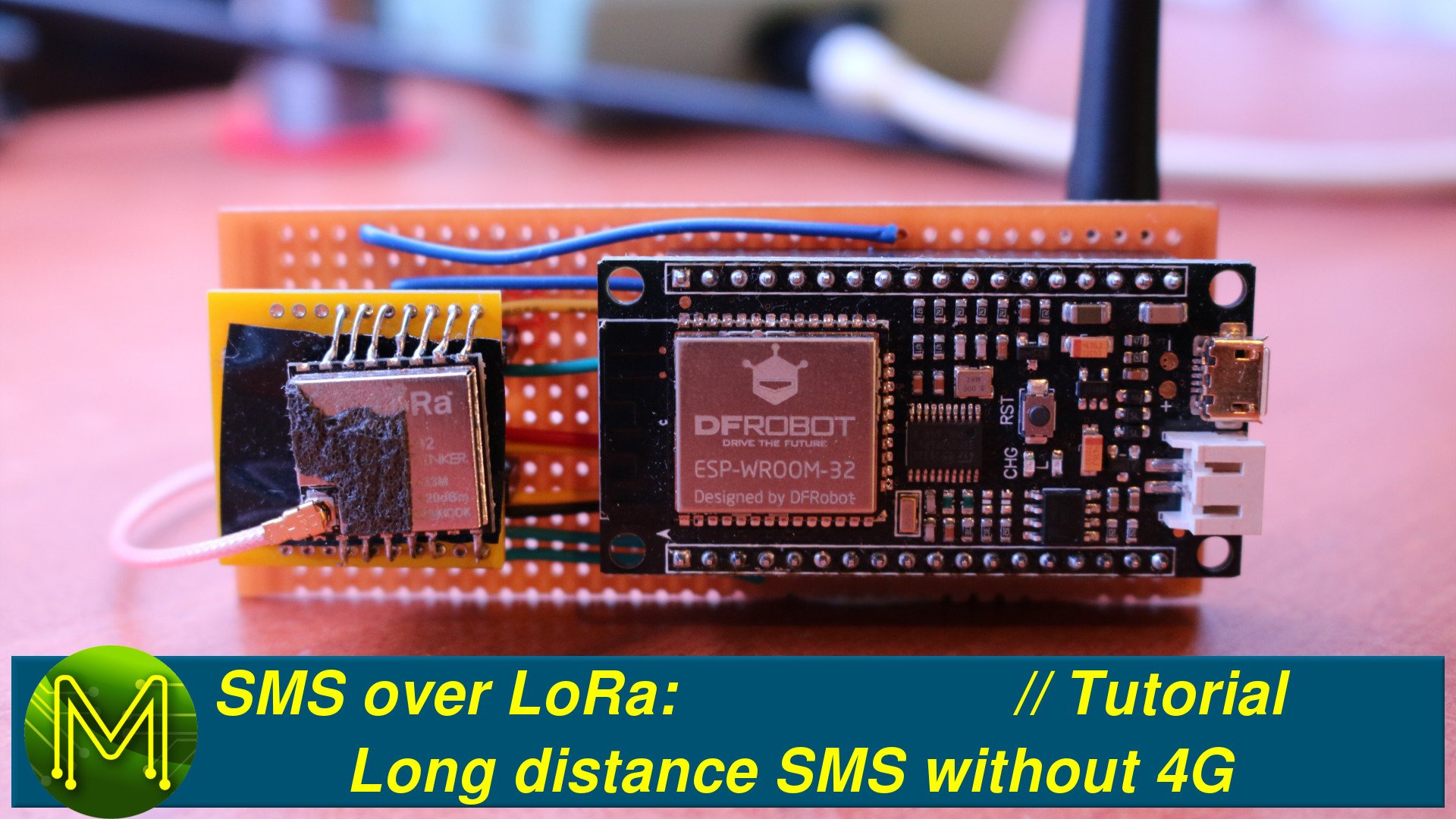
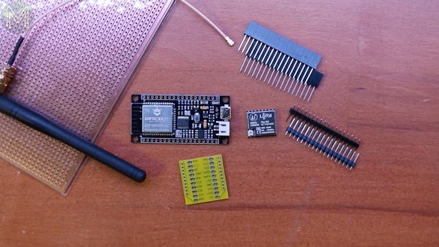
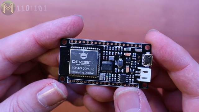
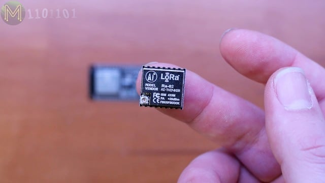
So, what do we need for this?I chose DFRobot’s ESP32 based FireBeetle. It’s similar to AdaFruit’s Feather, so you can use either. Whatever you choose, just make sure it has LiPo support.The LoRa module I used was from BangGood which was the Ra-02 module from AI-Thinker. This one has a handy uFL connector for external antenna.Then there’s the header pins that come with the FireBeetle and the strip-board or vero-board, external antenna,
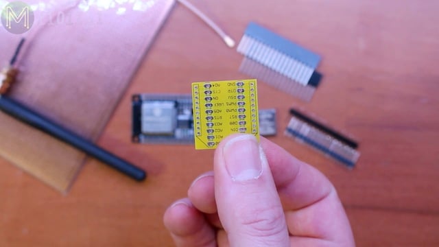
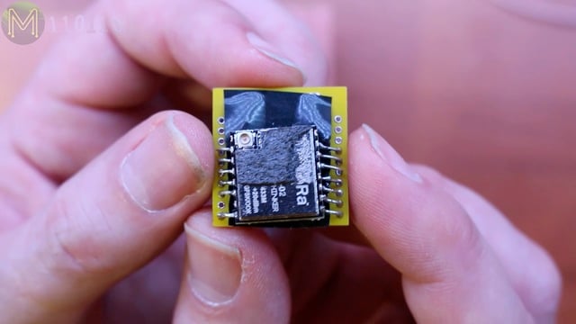
and since the LoRa module has 2mm pitch castellated solder points I needed a converter to standard pitch.Oh, and there’s also a LiPo battery.
The circuit
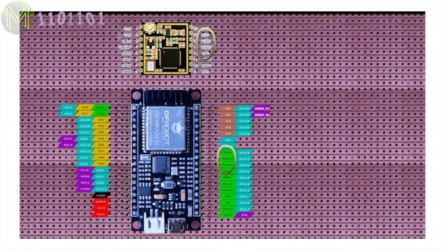
So, I need to plan where to place all these components to make it as small as possible with the minimum amount of soldering.
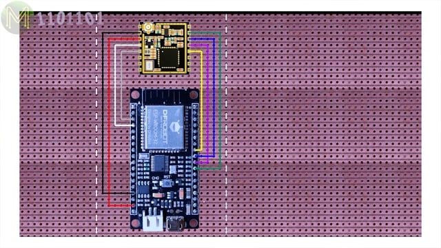
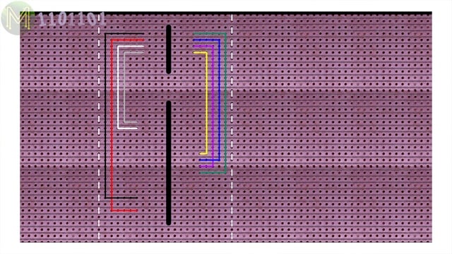
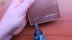
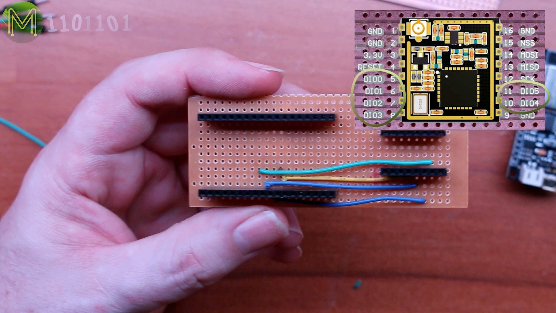
Placing the ESP32 here and the LoRa module here, means we have the SPI interface on the right side.Allowing easy connection of all the required signals and then I can cut the board to size here. Although it turned out to be smaller than that.Then all that’s needed is to dremmel out this bit.Construction
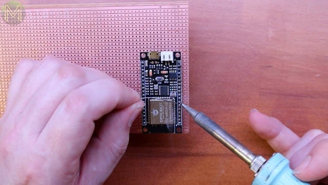
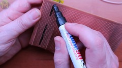
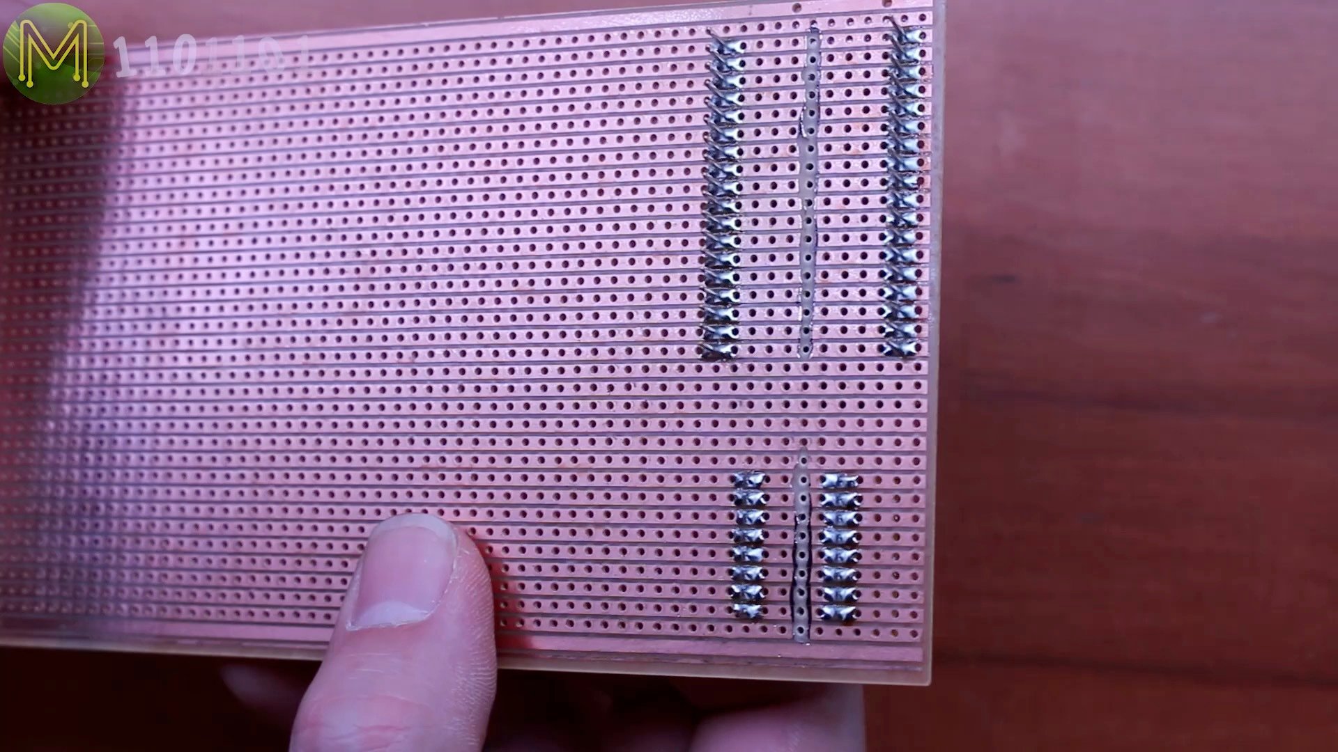
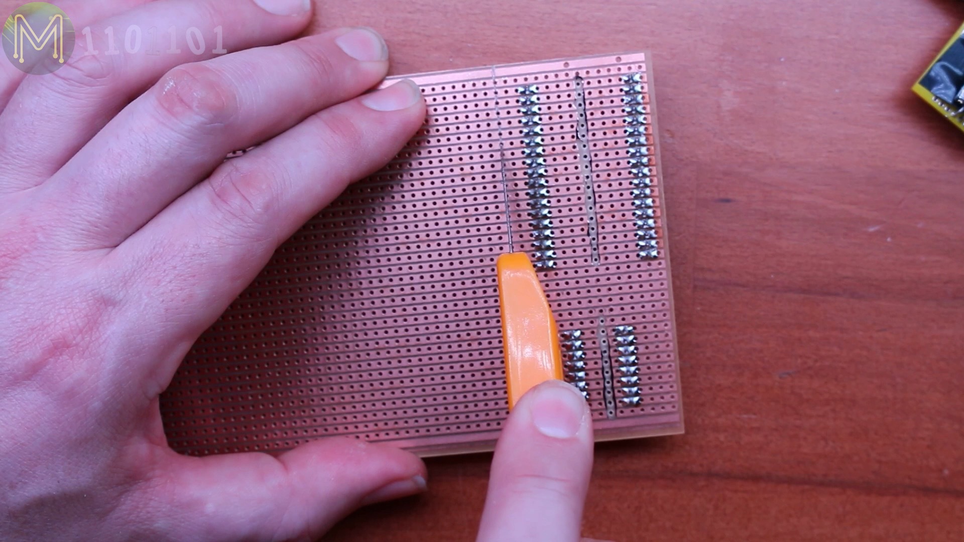
So, first solder up the FireBeetle. As always, I don’t solder the modules directly to the PCB, but use headers so I can re-use parts later if needed.The 2mm to 2.54mm pitch adapter board was a little tricky. As this particular board was designed for XBee modules, but I managed to get all the important bits soldered up.Then on to mounting up temporarily on to the strip-board so I can mark out where to Dremmel.
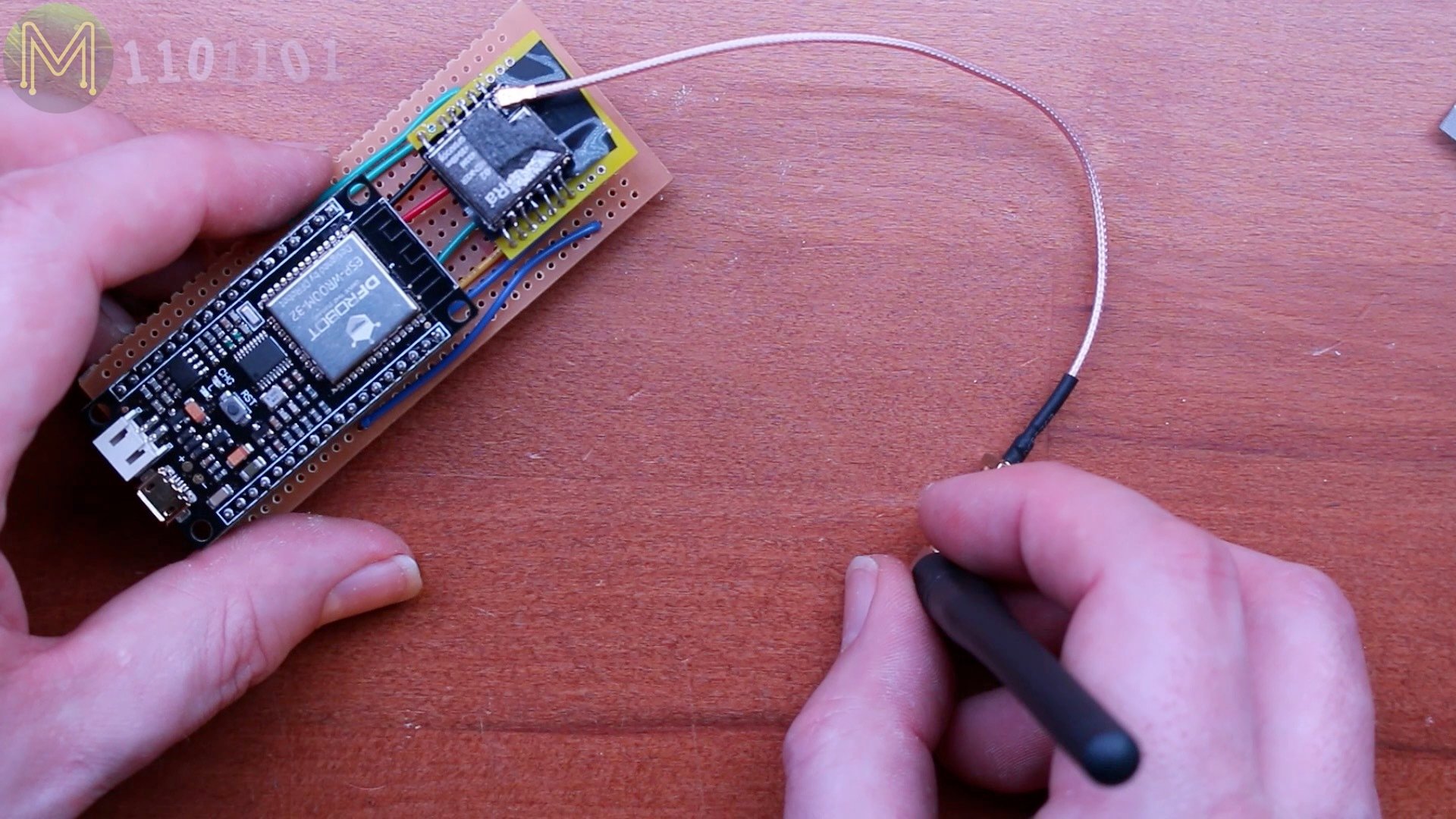
Then solder, solder, solder… solder, solder, solder, and you should be left with something like this.Then cut the excess board off. You’ll have to repeat this for the second module, but I won’t bore you with that.Then on to soldering up all the signal wires, which is pretty easy as there’s no cross-overs. I could have soldered up all the other DIO lines from the LoRa module here, but since there’s plenty of spare GPIOs, I can do that later. I only need DIO0 and SPI signals.Then chuck on the LoRa module, FireBeetle and lastly the external antenna.Testing
Next I wrote up some simple Firmware using several Arduino libraries. Check out my website for details. Once I went through a whole lot of boring testing I came up with some basic firmware that I flashed to both devices.
Which allowed me to connect to one of them from my phone and the other on my Mac. Then I could type in messages on one side and have them send over LoRa to the other side.Cool, eh?
Summary
Now bear in mind that this is a direct device to device link and it doesn’t use LoRaWAN.
I wanted to keep it as simple as possible.
Note also that it’s a pretty simple application. I plan to update the firmware to make it more robust and add features like Low Power modes, flash storage of messages and maybe a mobile app instead of using a browser.
So, stay tuned for updates on this project…

