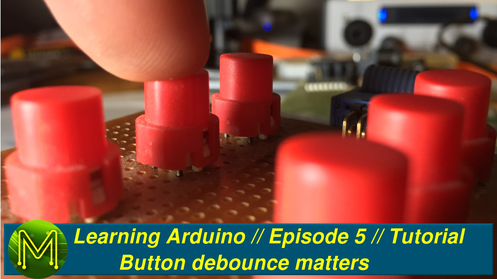
Learning Arduino: Button debounce matters // Episode 5 // Tutorial
Episode 5 of MickMake Mates tutorial into LearningArduino builds on previous episodes and takes you further into LearningArduino. This episode covers:
- What is debounce?
- What are some ways of resolving debounce?
- What does a capacitor do?
- The start of an Uber project that merges 3 tutorials into one.
If you have any questions or comments feel free to ask on Facebook or YouTube.
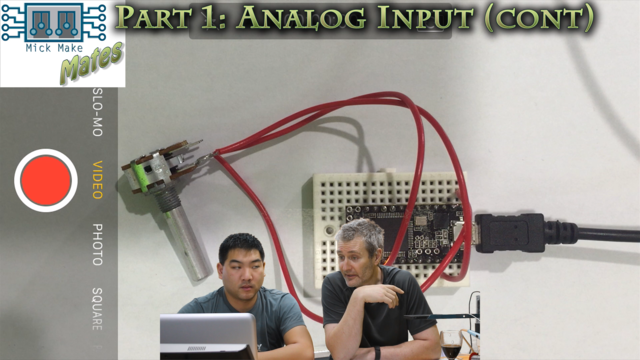
Part 1: Analog Input (continued)
This first part is a continuation of the Analog tutorial from Episode 4. This tutorial shows you how you can control the flashing rate of an LED based on the position of a potentiometer. The LED will flash faster when the pot is at a lower resistance and faster when it’s a higher resistance.
Now that you have mastered analog and digital inputs, and outputs, let’s take a look at combining several sketches into one for an Uber Project.
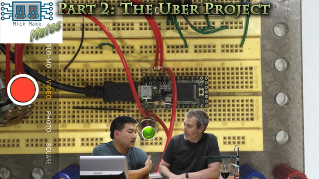
Part 2: The Uber Project
Now we get to the interesting part. I give Tim a project that combines several of the Arduino tutorials into one.
This will give him a good grounding for his project goals and extend his understanding of Arduino programming further. The three Arduino tutorials we will be using are:
- Button debounce - “File” -> “Examples” -> “02.Digital” -> “Debounce”.
- LED fading - “File” -> “Examples” -> “03.Analog” -> “Fading”.
- Analog input - “File” -> “Examples” -> “03.Analog” -> “AnalogInput”.
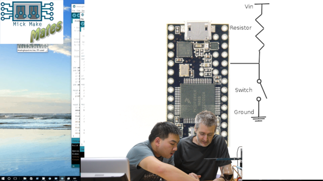
We will be using the following circuit. As mentioned earlier I was using a Teensy, but any Arduino can be used, just ensure that you check your pin assignments in the sketch that you create.
The Uber Project simulates a Nerf gun firing control, which is Tim’s final goal. It has one button, one pot and we’re making use of the onboard Teensy LED to simulate the “firing” of a Nerf dart. When you press the button 6 darts wil be fired in sequence. You can hold the button down for continuous firing. The pot will adjust the rate of fire.
I will post the circuit and software to Github once Episode 6 is posted as Tim has some homework to do!
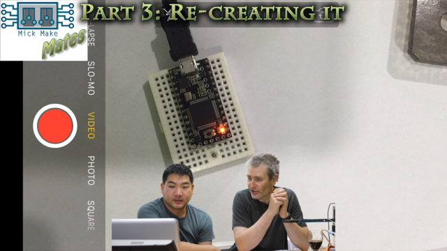
Part 3: Re-creating it
Tim was quite uncertain how he was going to emulate my project. When facing a seemingly complicated project the best way to handle it is to break it up into smaller areas or components that you can easily handle. This is called “black boxing” and works for really everything in life.
This next part we start to take my sample project and move components over.
The first “black box” that we need to get right is the button. This will be the starting point of our Uber Project and we will copy-and-paste code from the other sketches over to this.
Before we load up the “Debounce” sketch, let’s first load up the basic button sketch which is located under “File” -> “Examples” -> “02.Digital” -> “Button”. We will see shortly why we are doing this.
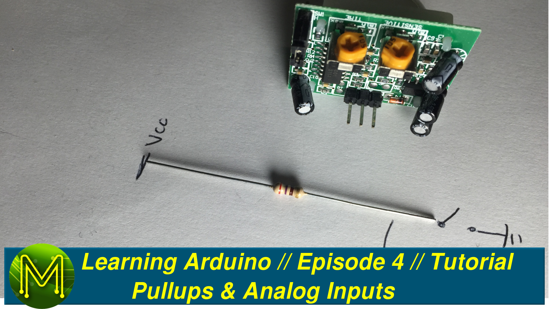
You want to connect up your button with a pullup resistor
Part 4: Handling bounce
Handling a button isn’t just a case of reading it’s state and responding to that input. We have to deal with button bounce. Let’s see why this occurs and how to deal with it.
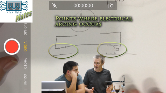
At the microscopic level a switch isn’t a perfect bit of metal connecting two wires together. There’s dirt, lumps of copper and other irregularities in the mechanism that causes what’s called “bounce”. Every switch and button has it.
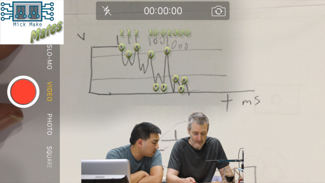
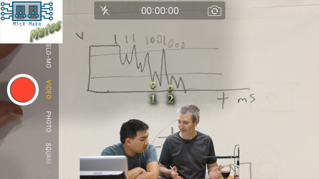
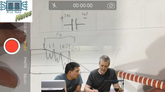
Remember the issues of the pullup resistor we had in the Episode 3? This same issue happens here. If you graph the voltage over time, you will see something like the following happen.
This means that taking into account the natural thresholds of the Arduino logic circuits you will end up with this.
That is; the arduino will see on it’s logic pin a sequence of:
1, 1, 1, 1, 0, 0, 1, 0, 0, 0
which the Arduino will decode as two button presses.
This is generally bad and you want to deal with this. There are four ways of “debouncing” a button:
By software:
You can either create your own debounce function within your sketch or make use of an already created debounce library. This is the preferred method as it doesn’t require any additional hardware and just a bit of your time.
Using a capacitor:
A capacitor is made up of two metalic plates where electrons are stored on one side. They are at the basic level a simple “battery”. We can make use of this stored energy of a capacitor by dampening the button press spikes. Attaching a capacitor in parallel with a button will allow you to do this.
Using a Schottky gate:
Schottky gates are special logic gates that allow for rectification of an input signal. Some MCUs have the capability inbuilt for this exact reason. These days using a Schottky gate is expensive, but if you are already using them in your project and have some spare for button presses then it makes sense to use them.
Using special debounce switches:
You can buy special switches that will debounce for you. However, these tend to be rather expensive and these days hard to find, but depending on your project needs you may have to look into one of these.
The next episode:
In the next episode Tim will be continuing the Uber Project further, moving components from my sample project over to his and enhancing his sketch, finishing up with his Analog Input tutorial, and then taking a look at writing his own sketch that will be a combination of three different sketches; The Button, AnalogInput and Fading sketches.

