How to make a Learner Driver Brake Assist // Project
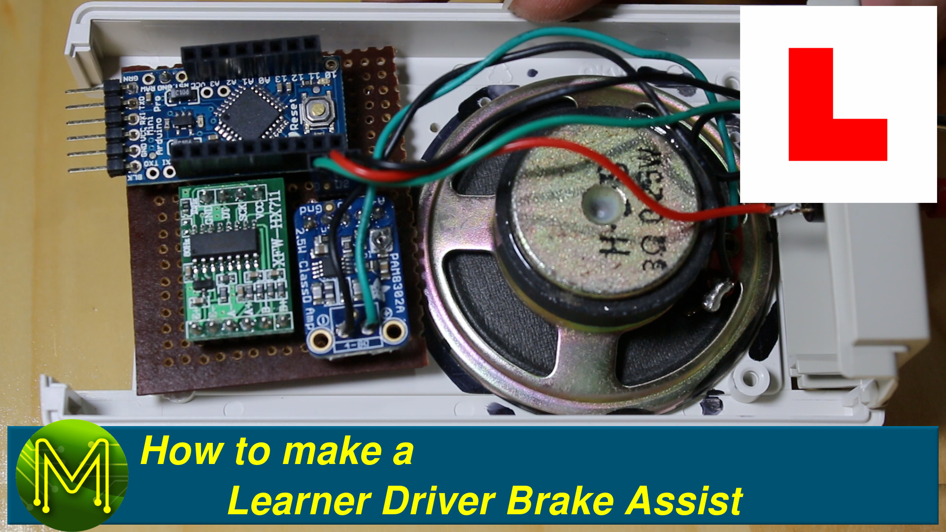
What can you do with an Arduino, bathroom scales, load cell amplifier and audio amplifier? Make a Learner Driver braking assist system, of course!
In this tutorial video I’ll be showing you what it does and how I made it. Leave a comment on the YouTube video if you make one yourself, how you did it and any improvements you made. I’d love to hear about it!
Warning
This device is not intended to replace or circumvent any safety devices. Even though it works for me, it is not something you should rely on. I made this device at my own risk. If you intend to make one yourself then you also do so at your own risk.
The problem
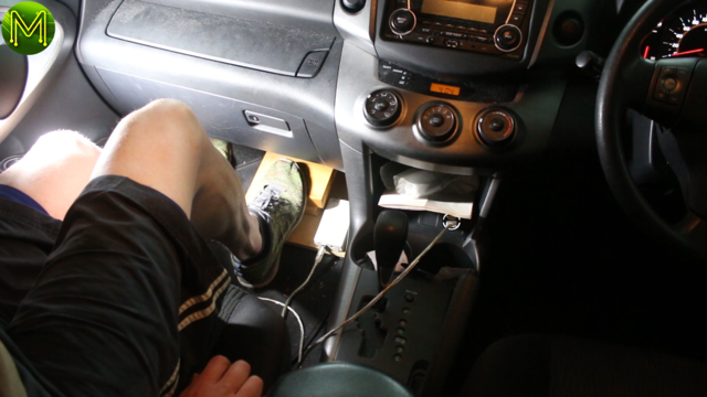
Learner Drivers often have difficulty gauging just how much to press down on the brake pedal. Often it’s a case of resorting to shouting louder to indicate just how much they should be pressing down.
Instead, this little hack provides audible feedback on just how much the instructor driver is pressing down on the fake brake pedal. A higher pitch means the Learner Driver really needs to apply a bit more pressure to the brake pedal. There are three levels. I figured any more than that and it’d get too complicated.
So here we go! I’ll go through the basics of construction but you can check out my video for a step by step guide.
Parts List
For this hack you’ll need the following parts:
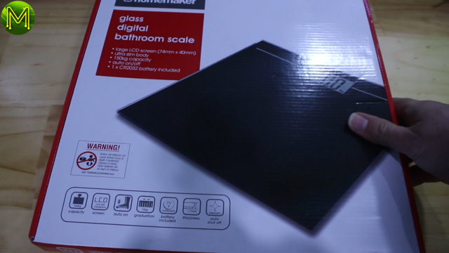
- Cheap digital bathroom scales.
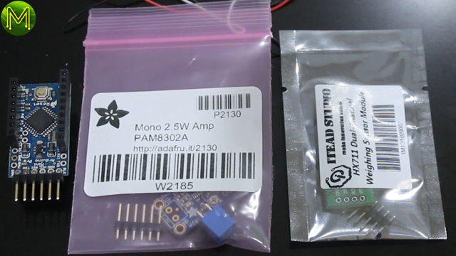
- Arduino Pro Mini - SparkFun AdaFruit
- 2.5W Audio Amp PAM8302A - AdaFruit
- HX711 load cell breakout - SparkFun
- USB connector - SparkFun
- And other misc wires and veroboard from SparkFun and Adafruit.
- You’ll also need some chunky timber to act as the fake brake pedal and some think timber to attach to the scales.
Deconstruction
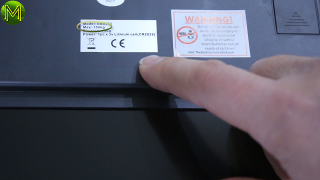
The first thing to tackle was the bathroom scales. I picked up a cheap one for around AU$9.
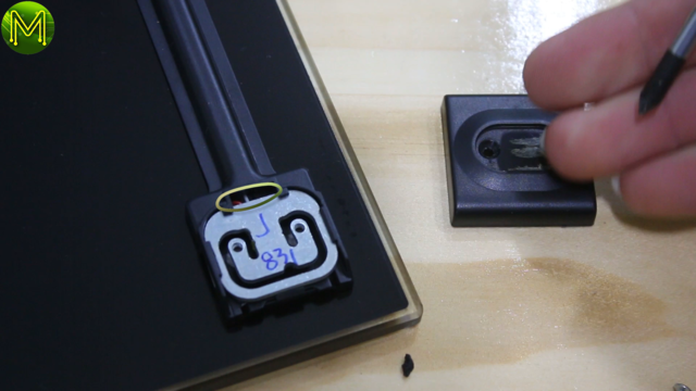
This is a cost effective way to get your hands on the load cell sensors. AU$9 gave me four sensors and already fixed to a plate! Each load sensor can handle up to 40kg. More than enough for my needs.
These scales had a glass plate. These sorts of devices have to conform to Australian standards, (which is fairly strict), and requires the use of toughened glass. That is: glass that will shatter into small bits and not large shards. If you build one yourself and are worried about this, then you can pick up cheap plastic scales as well.
I unscrewed the feet off one of the load cells to see what I actually had.
Turns out I had a typical three wire load cell.
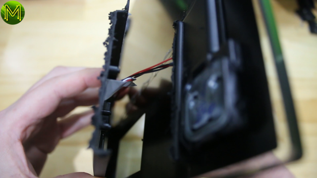
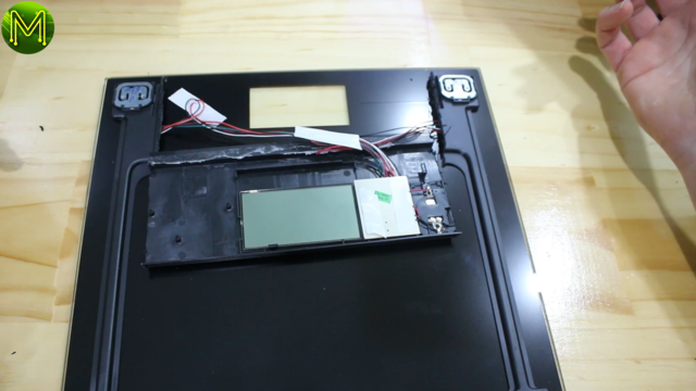
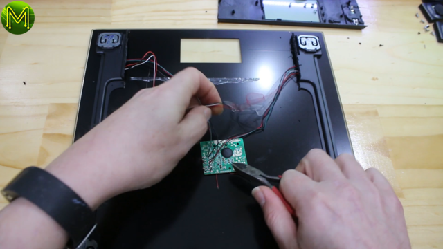
Next I dremmeled off the plastic case housing the electronics, cut the circuit board off and threw it away.
Breadboard time
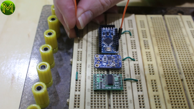
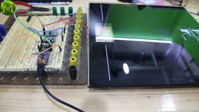
Next I solderd up headers to all the breakouts and wired up everything onto the breadboad.
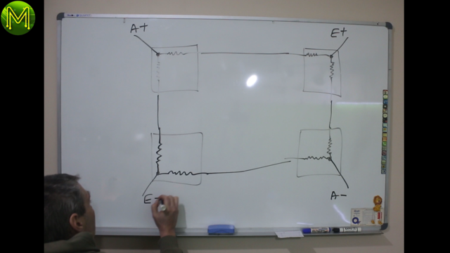
The tricky bit is figuring out how to wire up the Wheatstone bridge. A Wheatstone bridge is a way of measuring an unknown resistance of something… At the basic level.
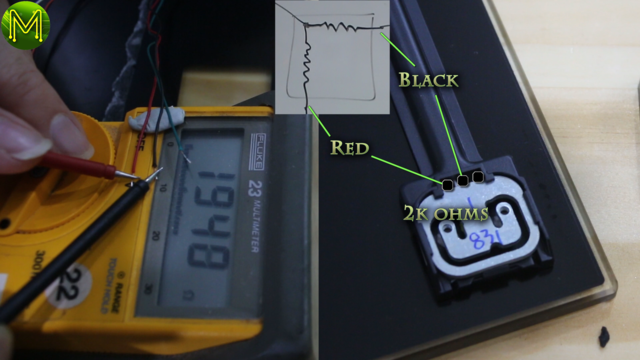
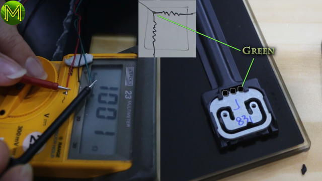
So I needed to figure out which wire was going where. This is easily figured out by measuring the resistance between each of the wires.
The wires with the higher resistance will be the two outer poles and the third will logically be the middle pole.
I wired everything up and wrote a simple Arduino sketch to start testing.
Coding up
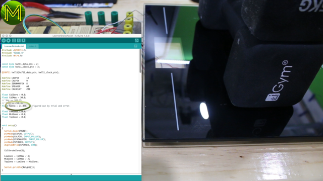
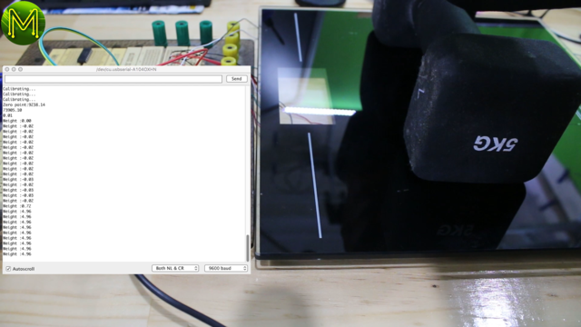
I wanted to be able to translate a force applied to the scales to a real weight. With some trial and error, I eventually arrived at a magic number and could display weights to a reasonable level of accuracy.
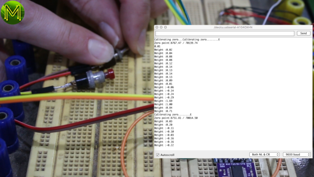
Then added a button and a switch and used these in my code for calibrating the scales.
When the scales first power on they need to be reset to a zero or resting point. Once you have that you can then set the maximum point which is essentially the hardest you can push down. I set this to a fairly good default, but sometimes you might want to recalibrate.
So when the toggle switch is down and you press the button it calibrates for zero. Flick the toggle up, press down on the scale and press the button will set the maximum point.
Easy!
Soldering and cases
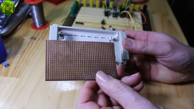
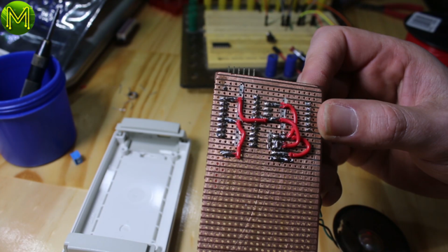
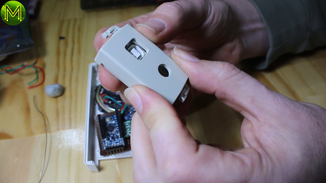
Now that everything was working I moved it all over to something more permanent. I found some Veroboard and a good sized case and soldered it all up.
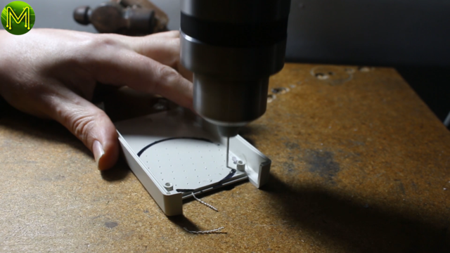
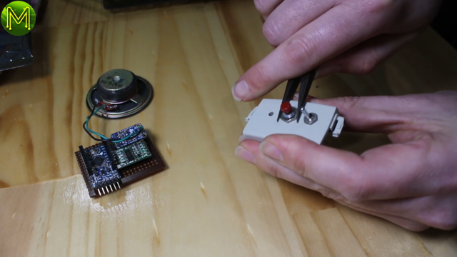
Drilled out speaker holes, switch holes, and a bit of dremmel activity to make everything all fit in.
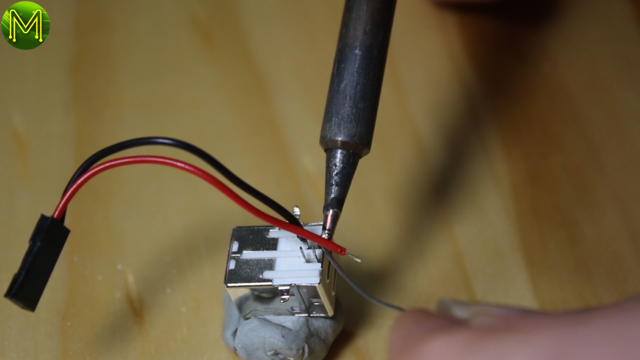
Power is provided by a cigarette lighter to 5v USB adaptor connected to a USB port on the box.
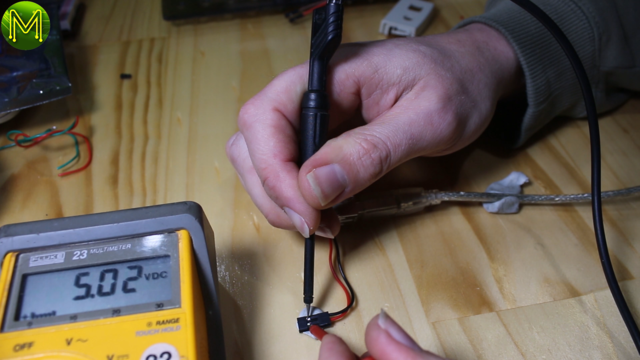
Just double checking to see I had my wiring correct. Don’t want to fry things. You can find what wires to connect up to the USB socket just by googling. There’s tonnes of examples.
The Pedal
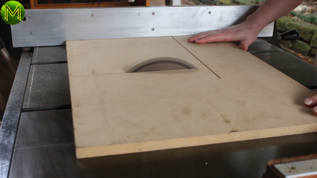
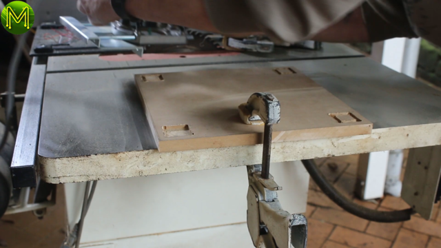
Next on to the fake brake pedal. I marked out and cut some thick MDF to size.
Then marked out and routed a place for the scale feet to sit into.
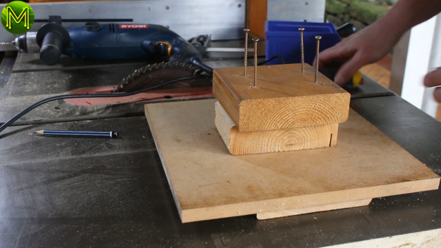
and screwed in some old cedar offcuts as the actual fake brake pedal.
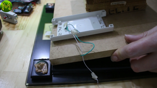
Then back inside I poked the Wheatstone bridge wires through from the bottom and fixed it to the feet of the scale with liquid nails.
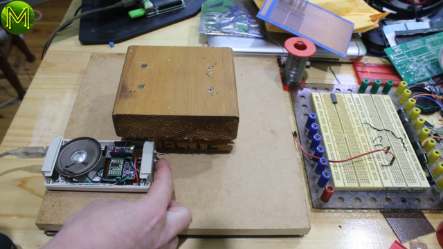
Then managed to fit all the components in.
And it works really well!
Documentation
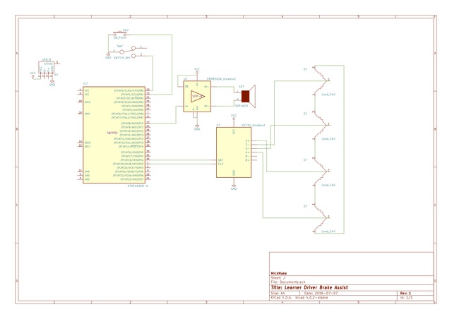
Supporting docs for you to build your own. Send me a message if you have questions.
Check out the GitHub source code.
Click on the schematic to download a PDF version.

