Build a talking Alarm Clock synced to Google calendars. // Project
My original project 30 years ago was to build a talking Alarm Clock, which was based on a 6502. This is a revamp of that project. Interesting to see what can be done so easily these days!
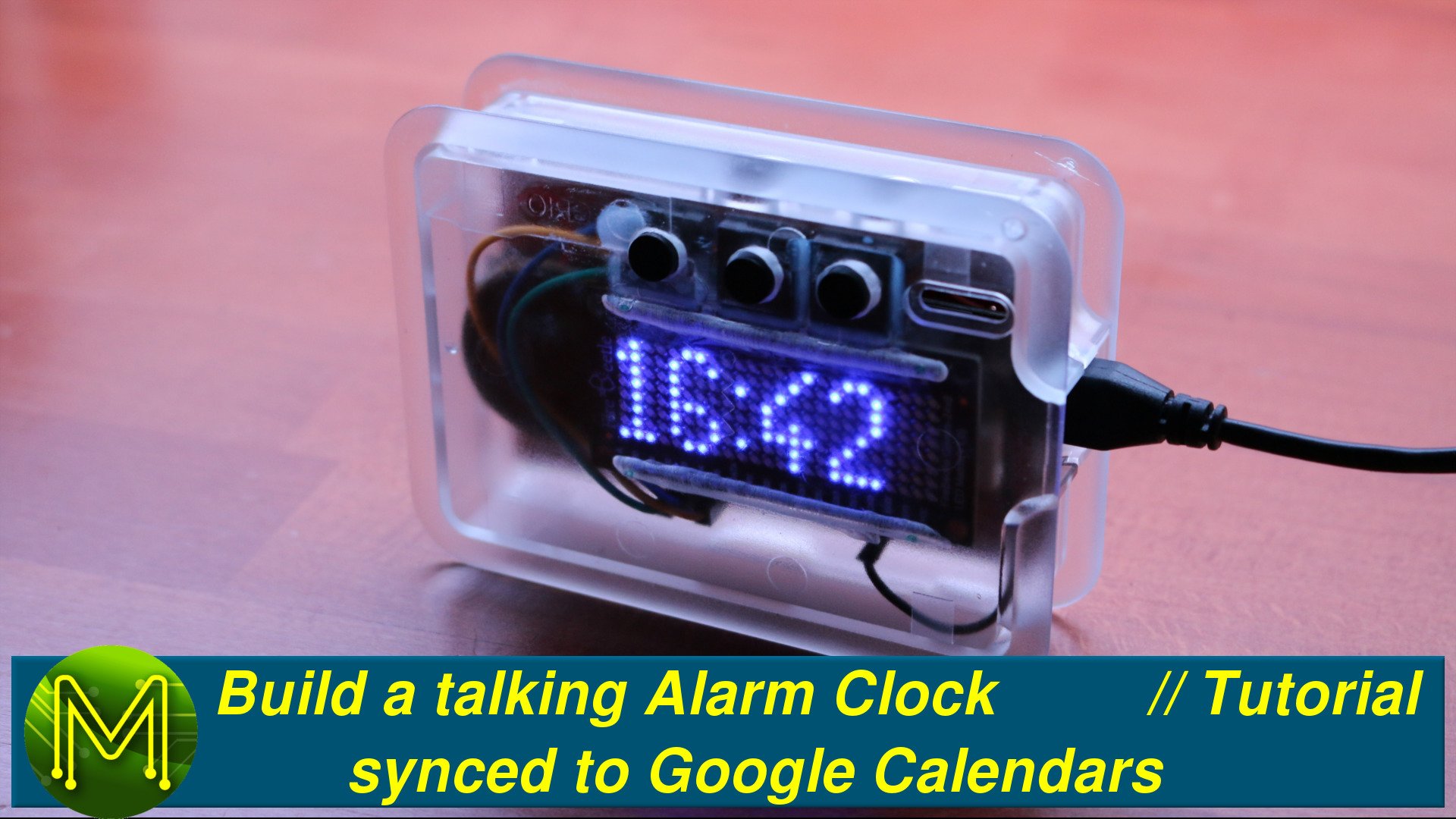
The old clock
So, why am I doing this?
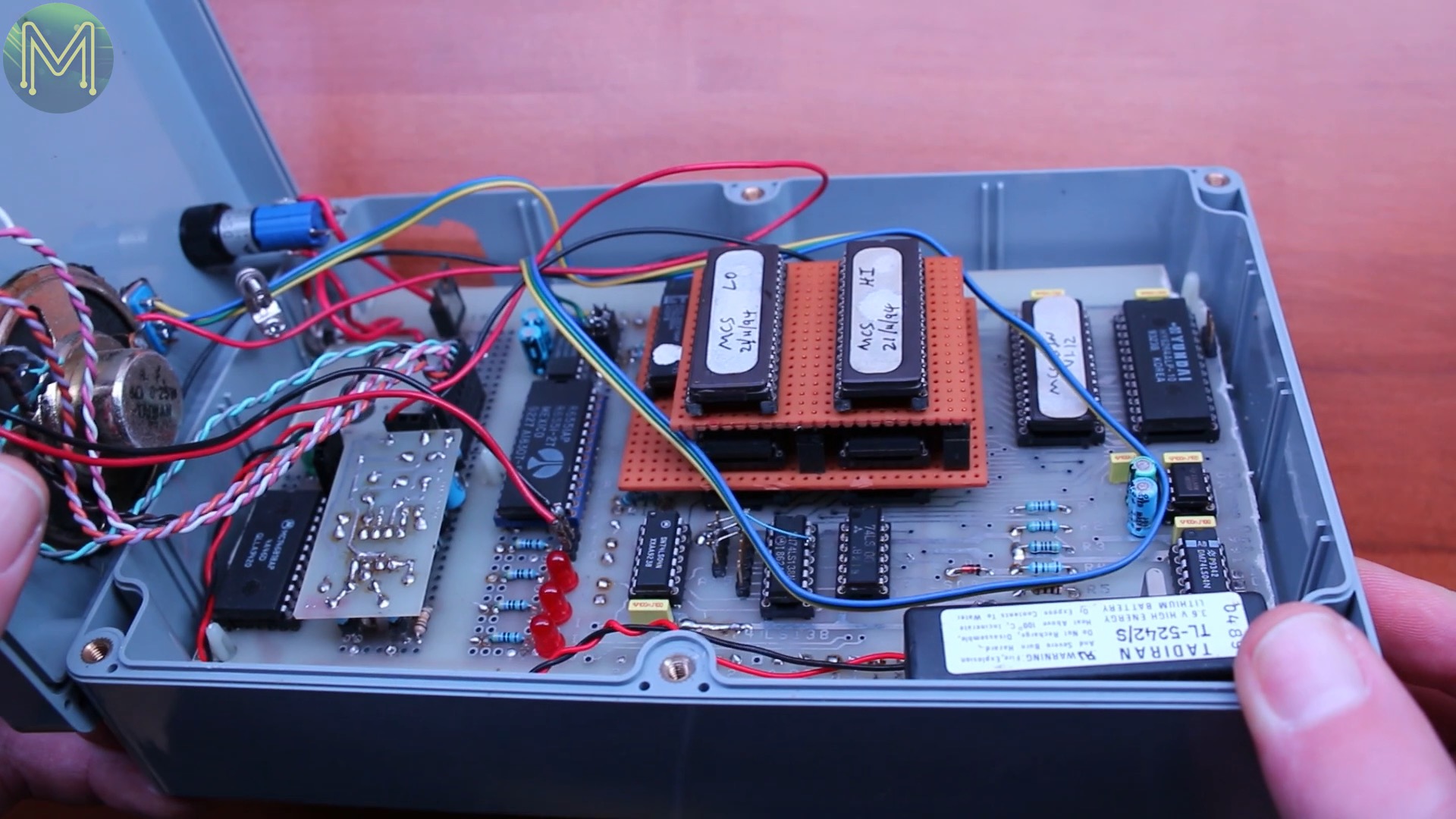
Well, I made a similar talking alarm clock back in the 1980s using a 6502. Sound samples were stored on EPROM which was bank switched in.
The 6502 doesn’t have much address space. Only 64k to play with I had to fit not only my code but sound samples. I managed to squeeze my code into the lower 32k and the sound samples were stored on 4Mb EPROMs and paged in to the 6502’s upper 32k address space.
Each sound sample managed to just fit in. I had just enough sound samples to say every possible time and date combination as well as my baby daughter crying as the alarm.
So, thirty years later I want a bit of automation.
Prototyping
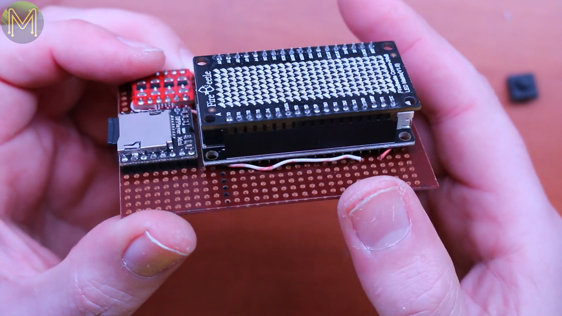
The new clock will be based on DFRobot’s FireBeetle, which is an ESP32 based board, a 24x8 LED matrix and a mini MP3 player to hold the sound samples on SD card.

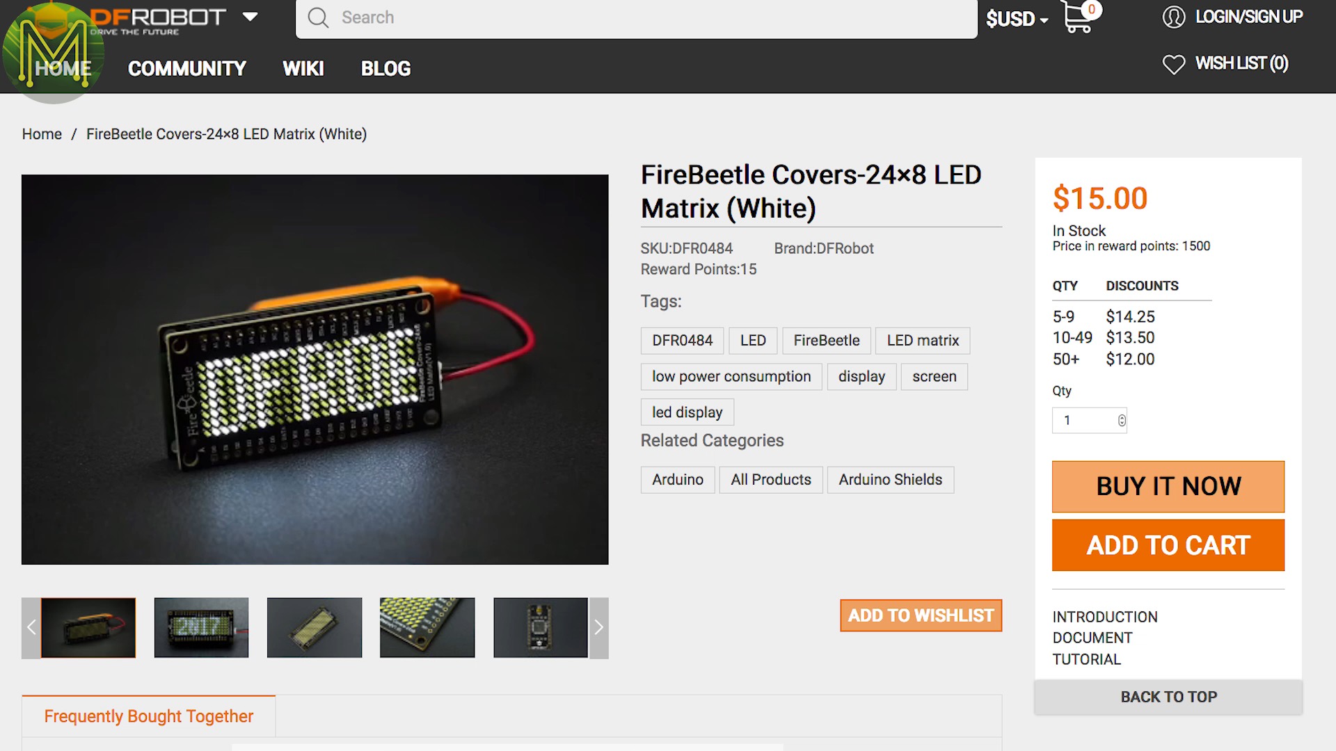

The FireBeetle is very similar to AdaFruit’s Huzzah and in fact you could use it instead.
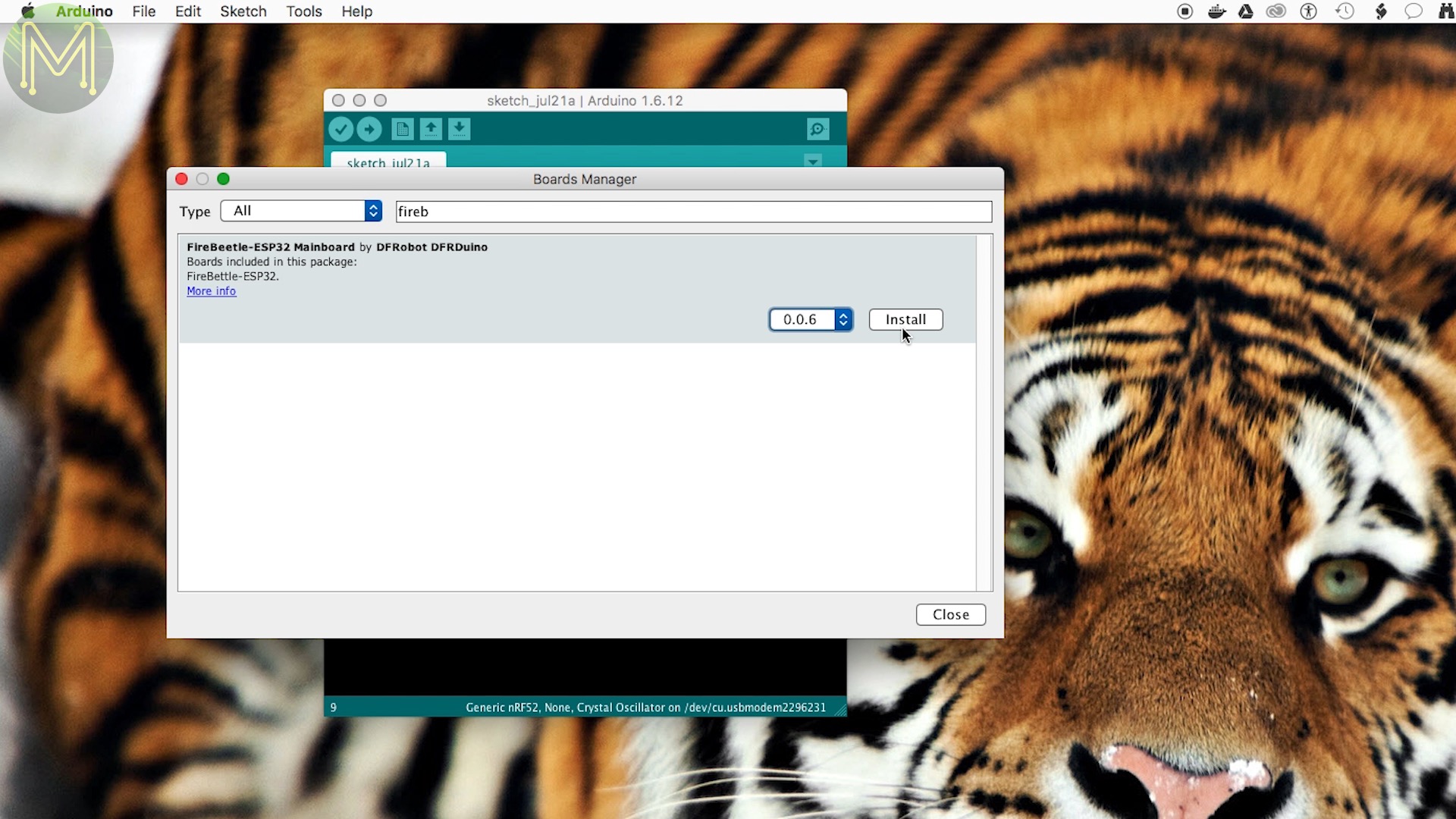
Using the Arduino IDE, you will have to of course add in the FireBeetle URL into the Board Manager and install it. Then on to a day of coding up everything…
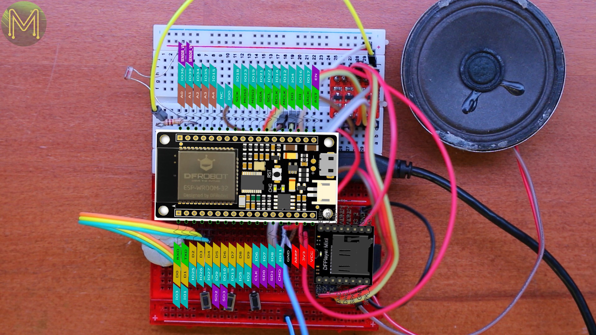
Once finished I loaded it up onto the FireBeetle on my prototype board.
It has all the essentials; FireBeetle, MP3 player, speaker, logic level converter and there’s a small LDR that can adjust brightness of the display automatically and three buttons to do stuff with.
So, on to the making it more permanent.
Building
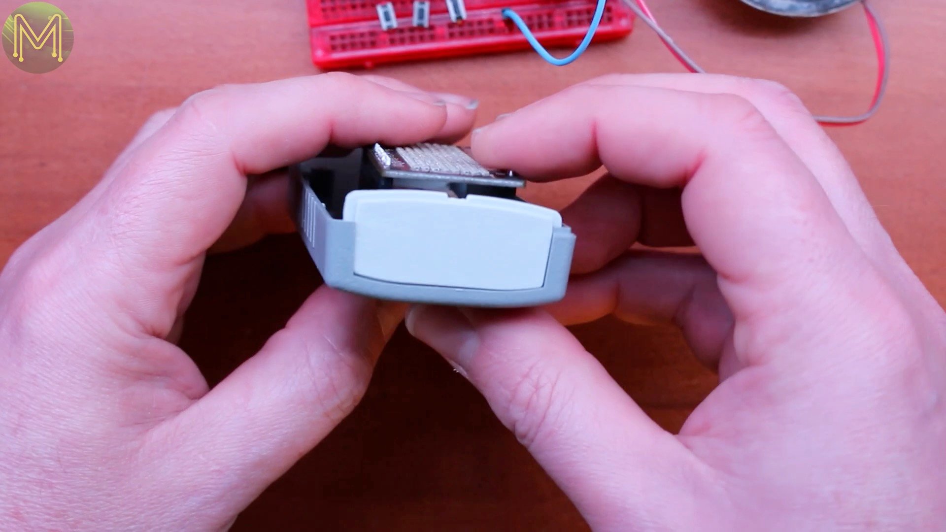
Finding a box that fits is always the difficult part. I don’t yet have a 3D printer so finding one that fits is a bit hit and miss, but the last one looks pretty good and will just fit everything.
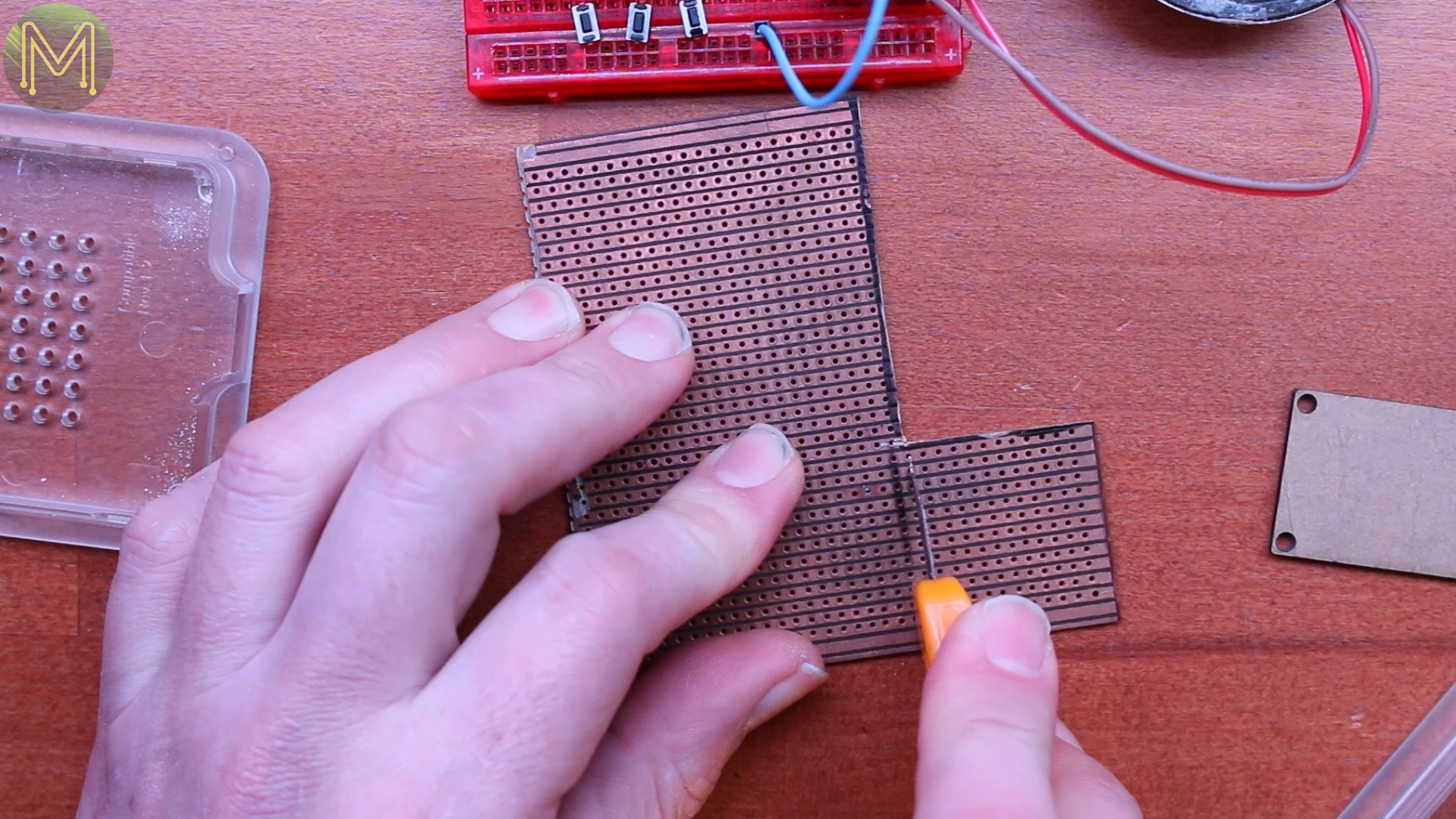
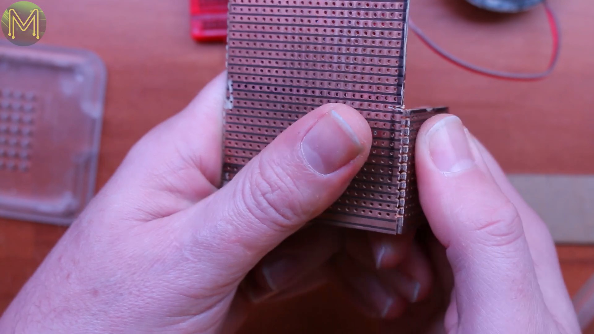
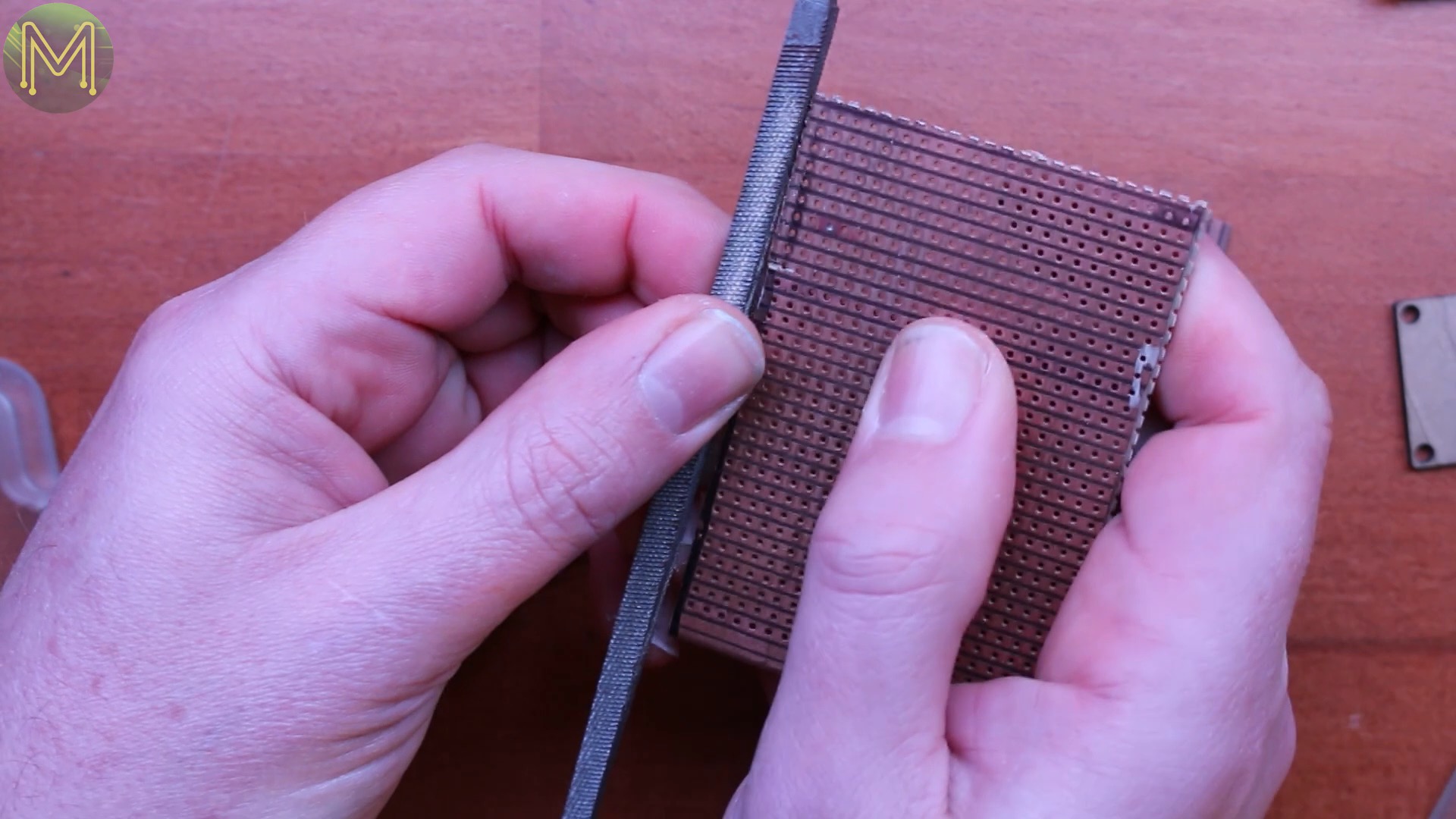
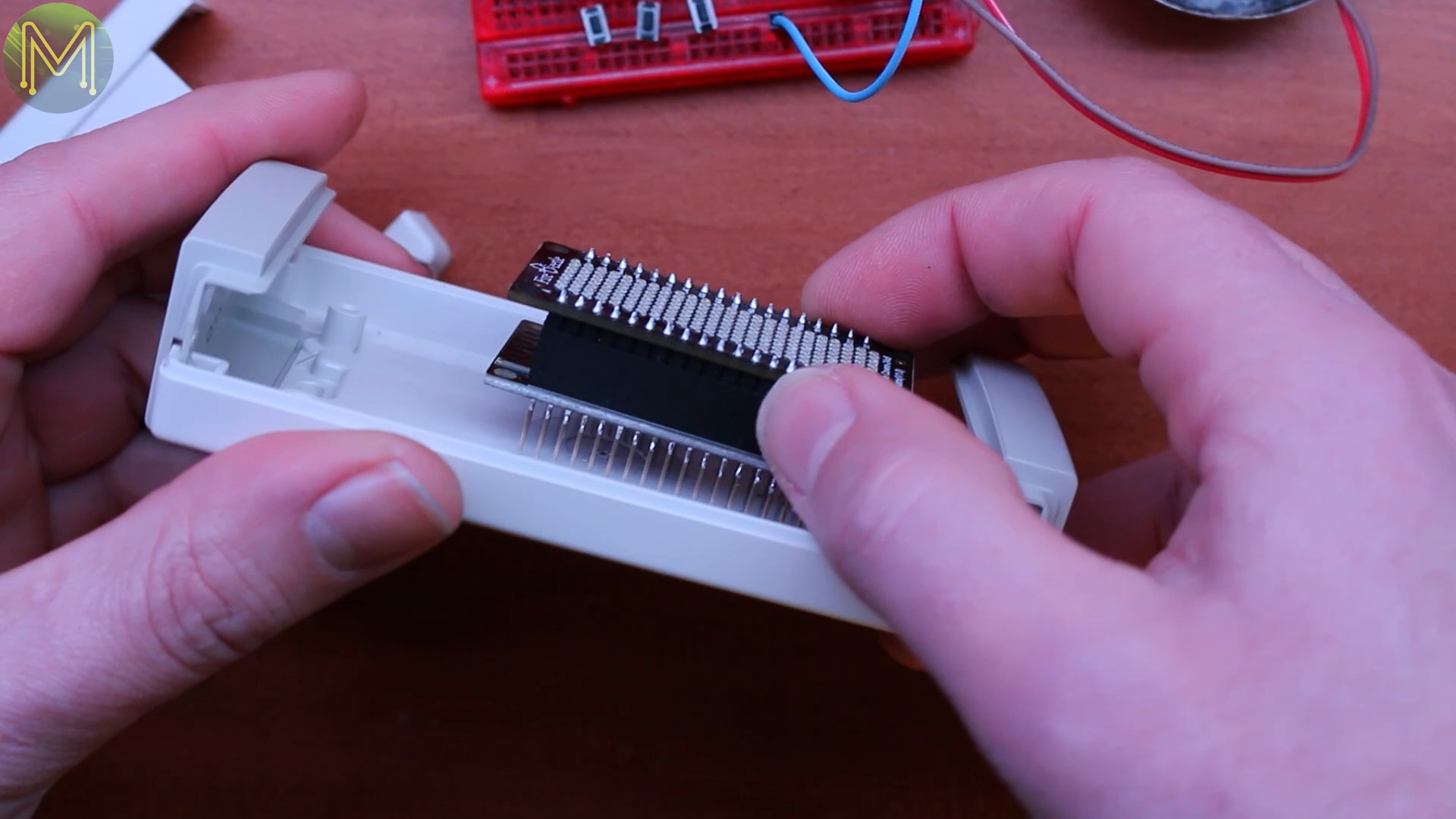
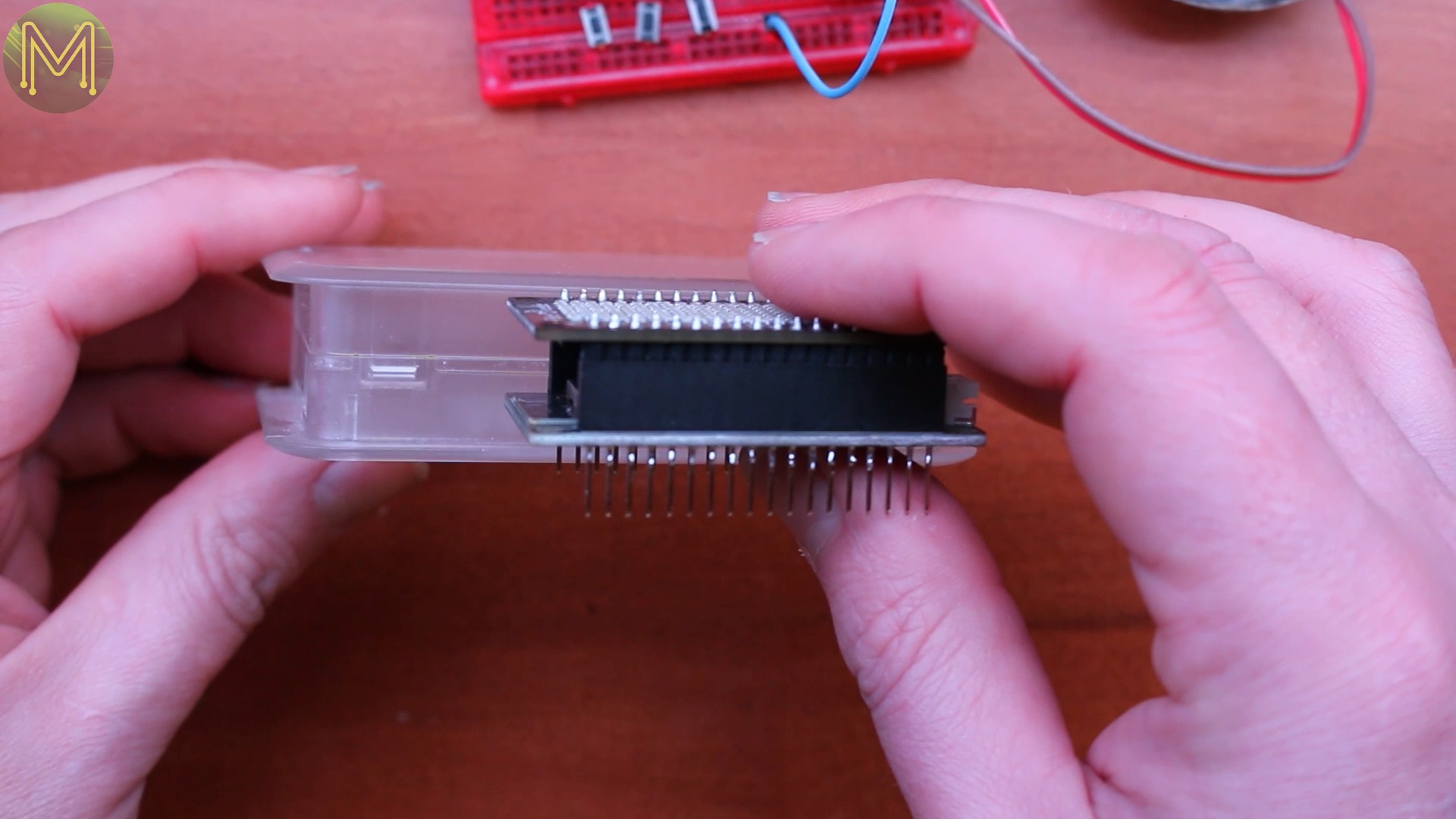
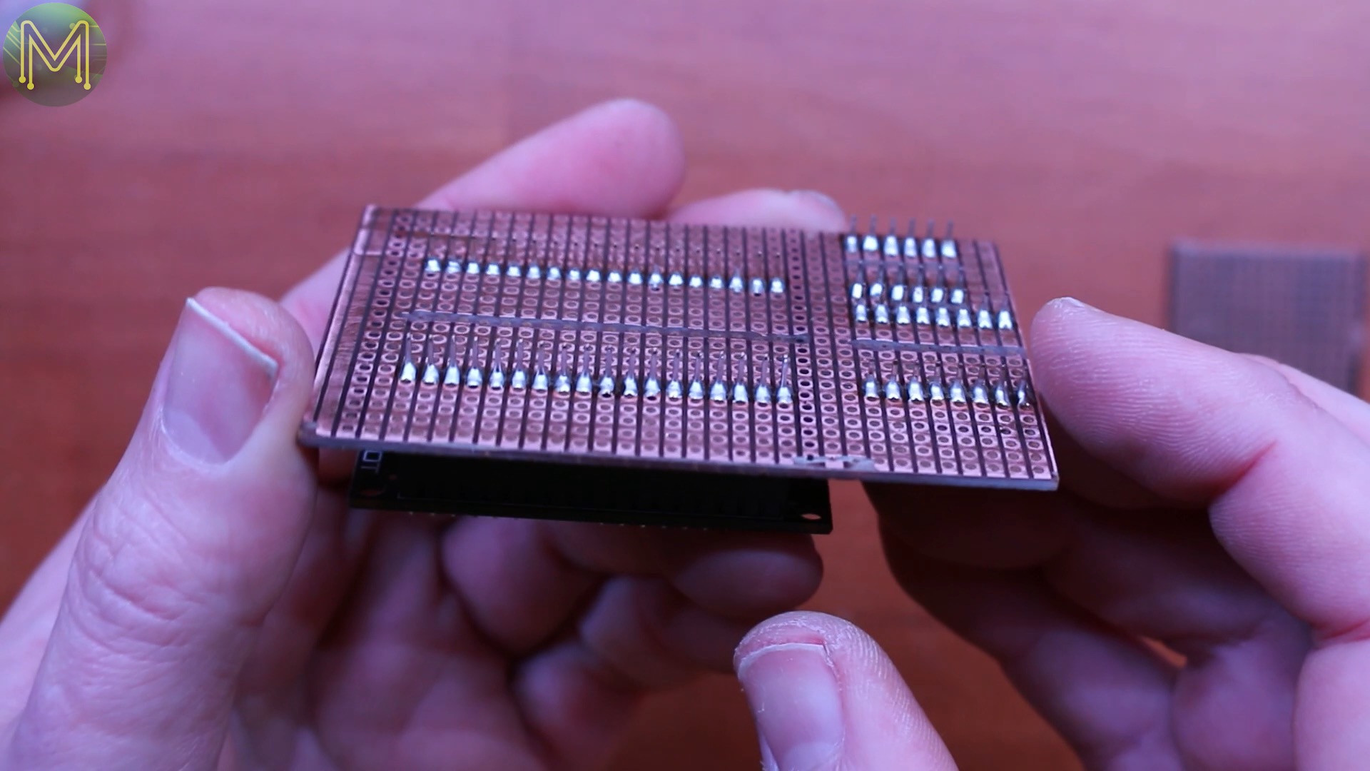
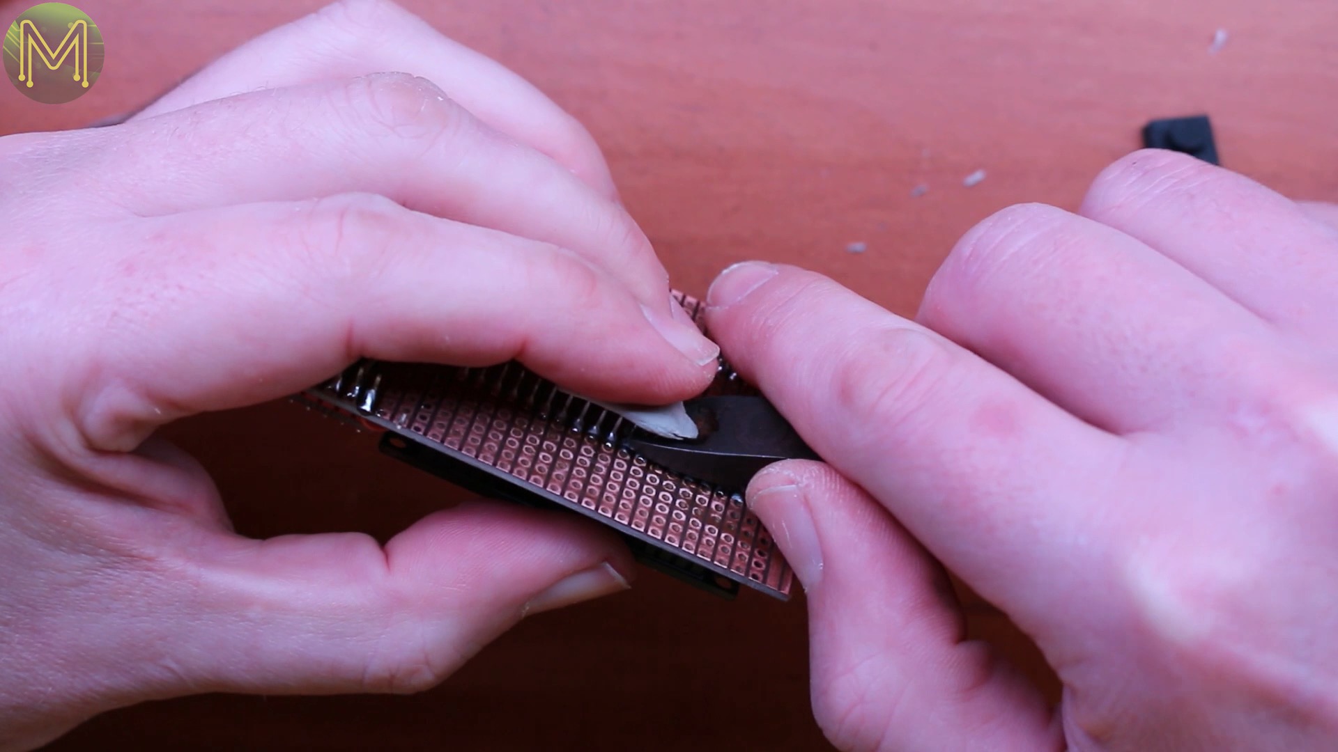
So I marked out some veroboard, scored and snapped it to size. Then filed down the rough edges,
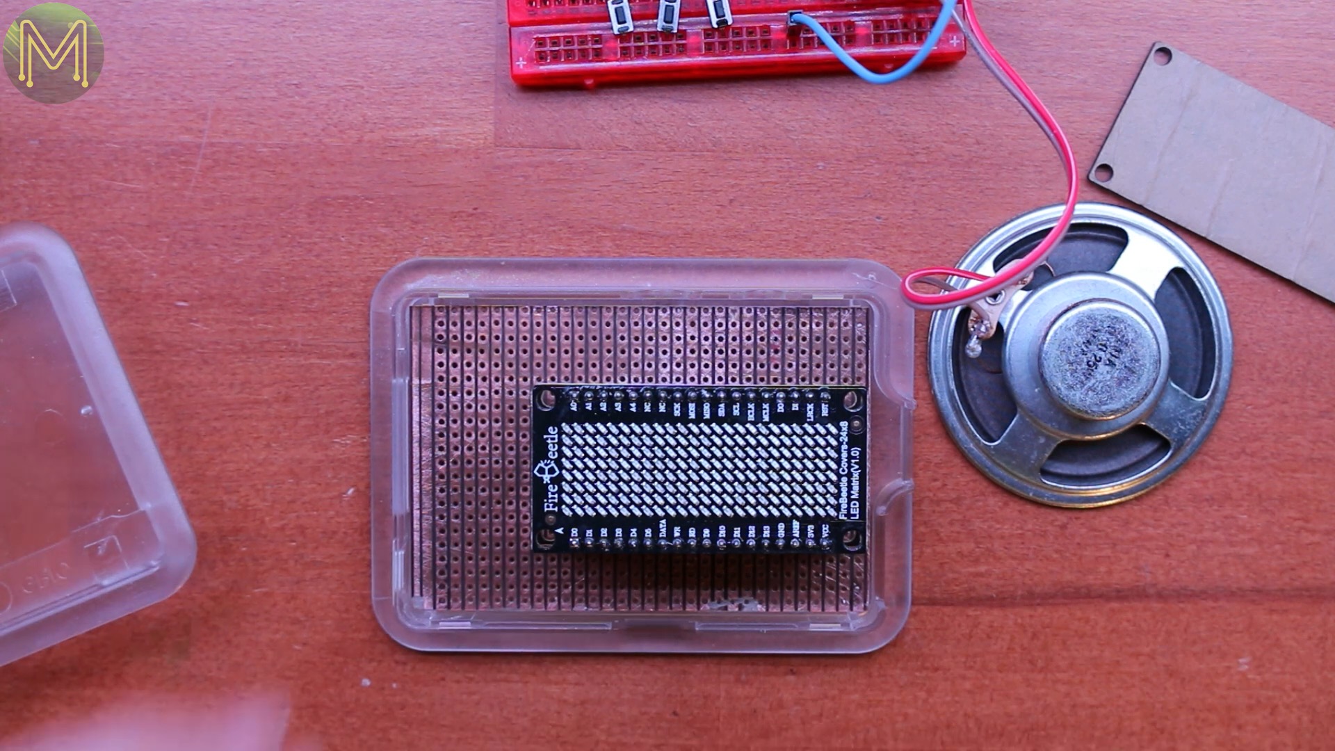
and it fit in well. However, with this small case it was difficult to fit in my large speaker so I used a smaller one I picked up from my a junk pile.

I reckon placing it just above the MP3 player would fit well.
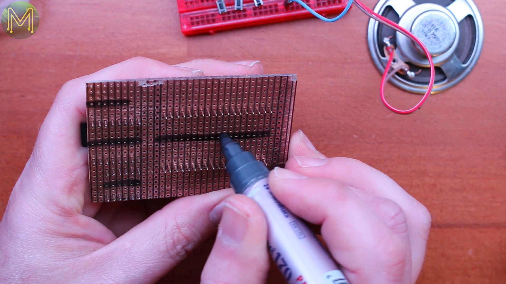
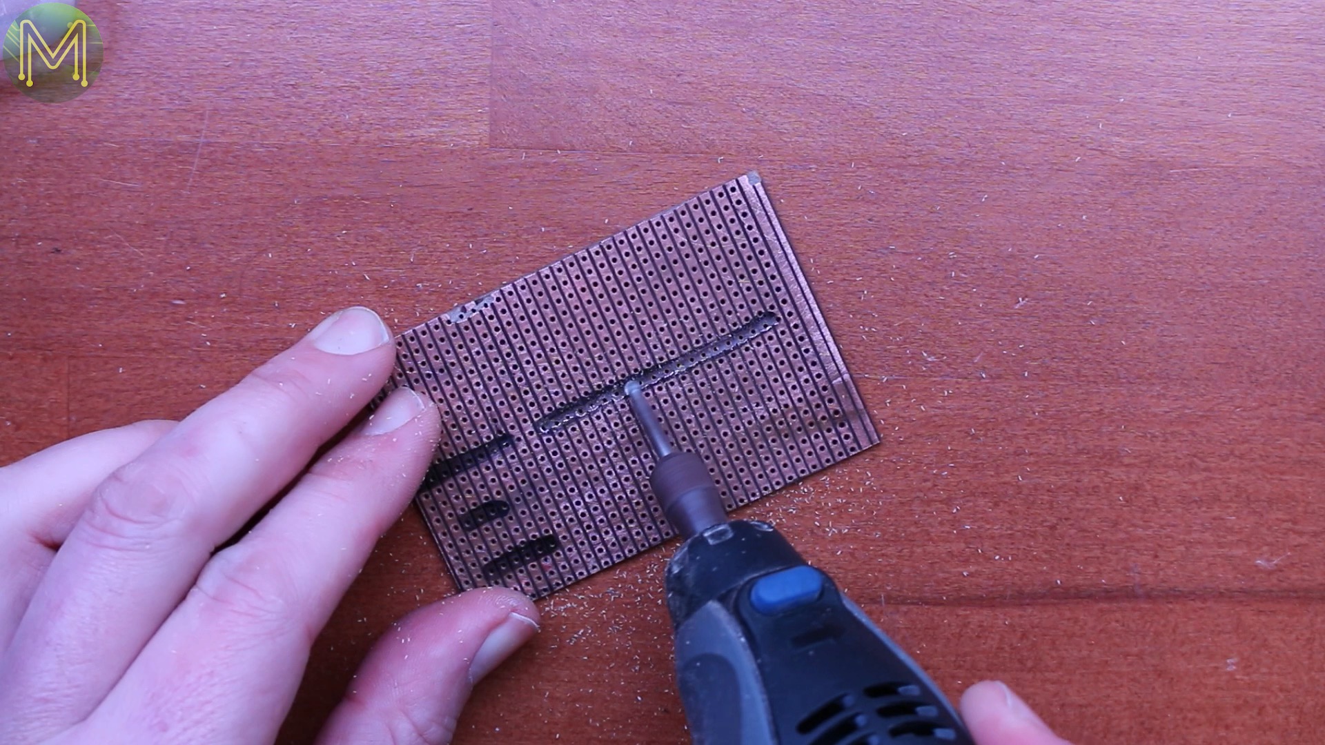

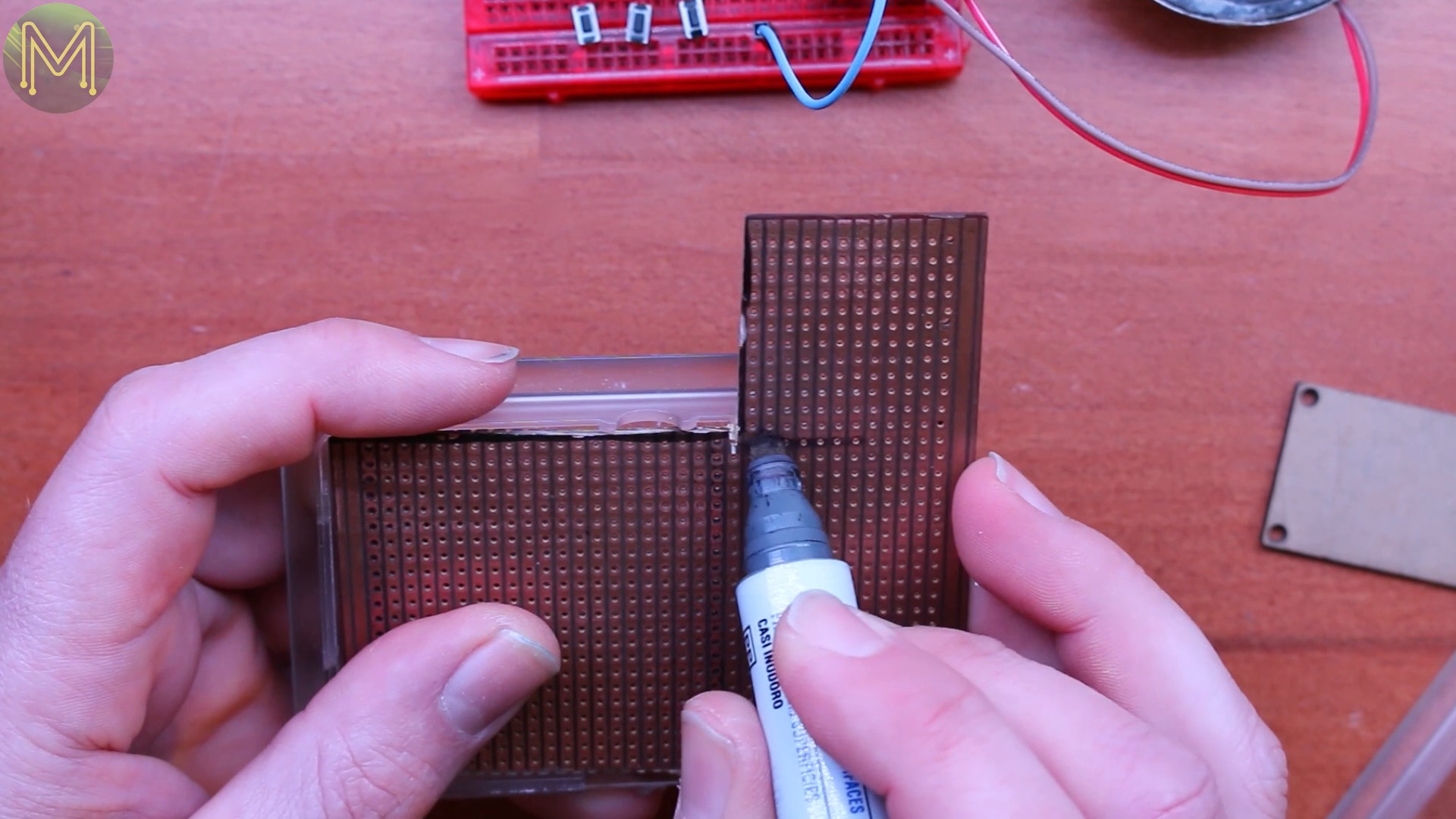
On to marking out and dremmelling the copper tracks that I don’t need connected up, and then cleaning it up with a bit of metho.
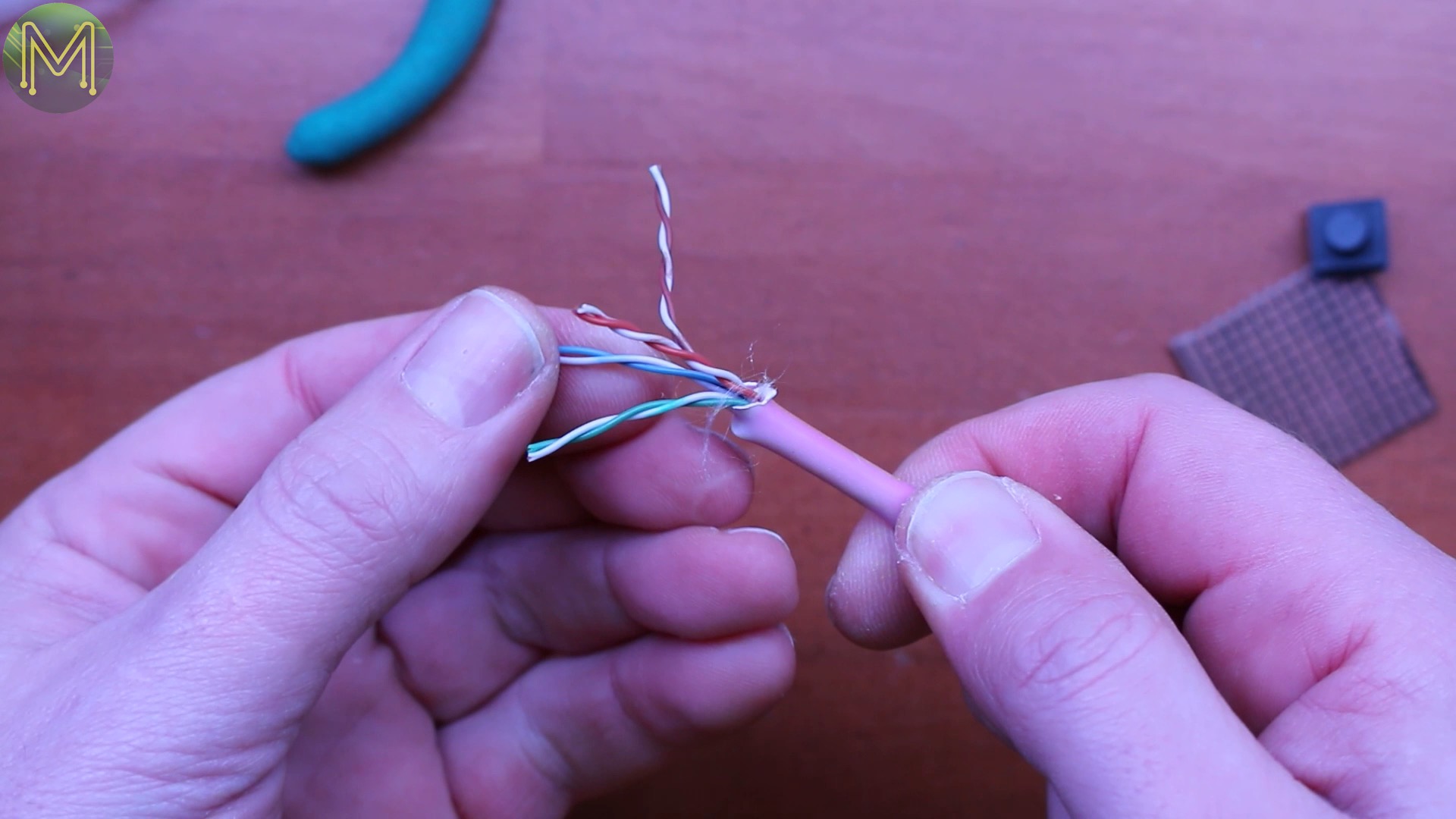
I’m starting to use old Ethernet cable for hookup wire as it’s a nice solid core and cheap.


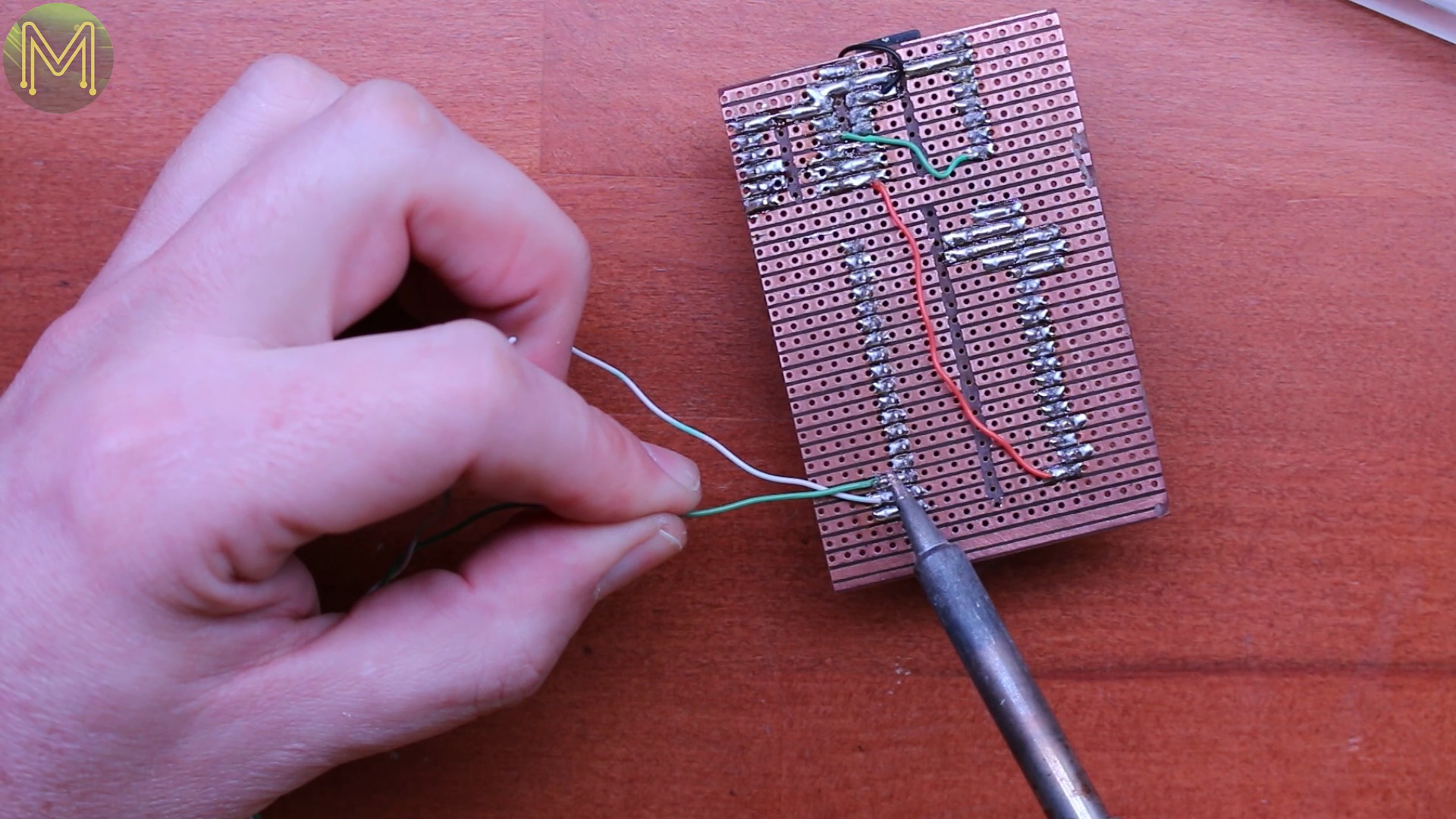
This time round I soldered everything directly to the veroboard as space was tight. First I soldered up the logic level converter to the MP3 player. Then on to soldering up the MP3 player busy line. Then the power and ground lines from the ESP32, which I ran on top. Every time I solder up a connection, I’ll remove it from the breadboard just to make sure I have everything.
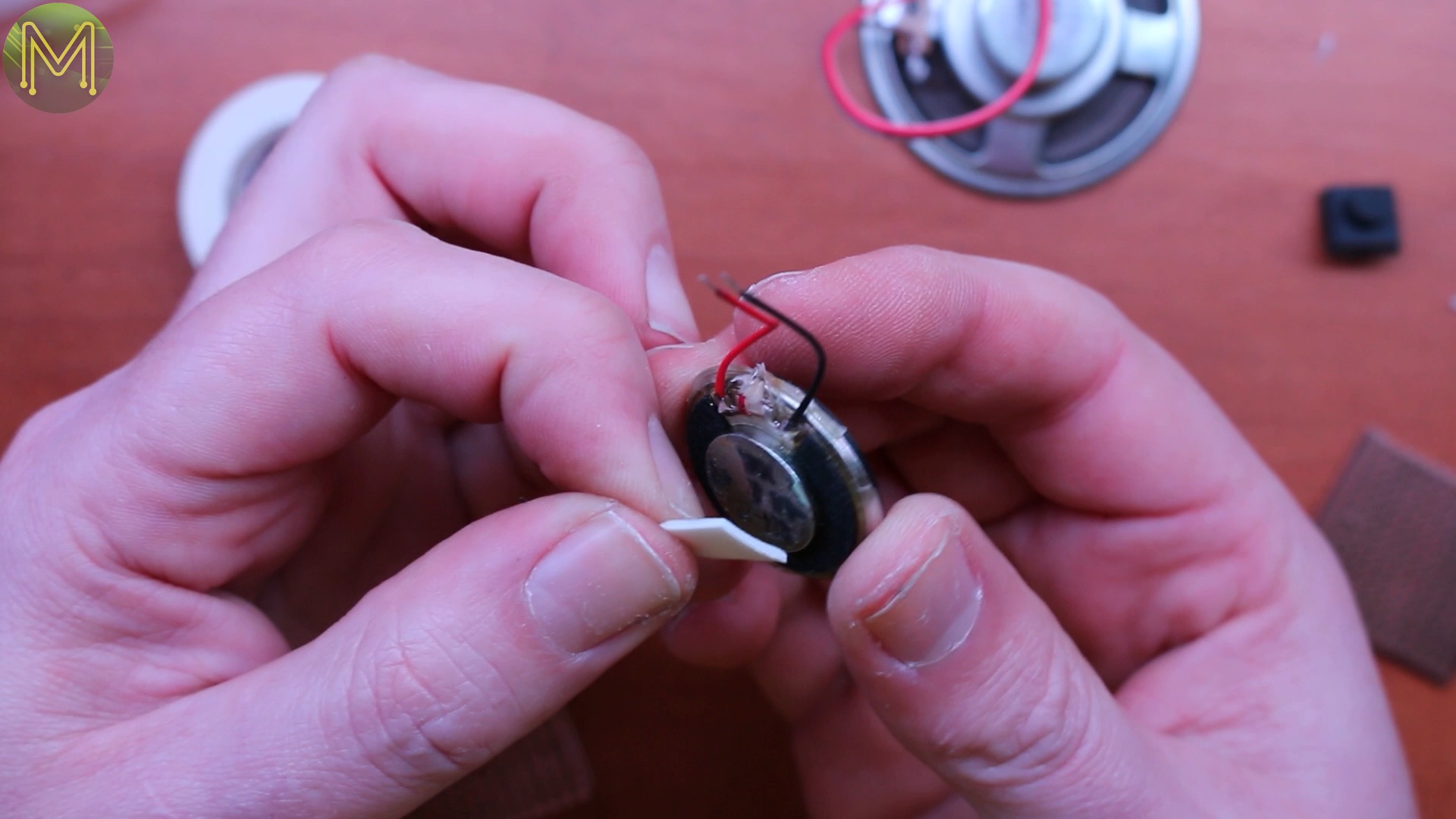


The speaker was held in place with double sided tape, and then soldered up as best I could. When I do this again I’ll make sure the speaker comes out the top and not out the side.

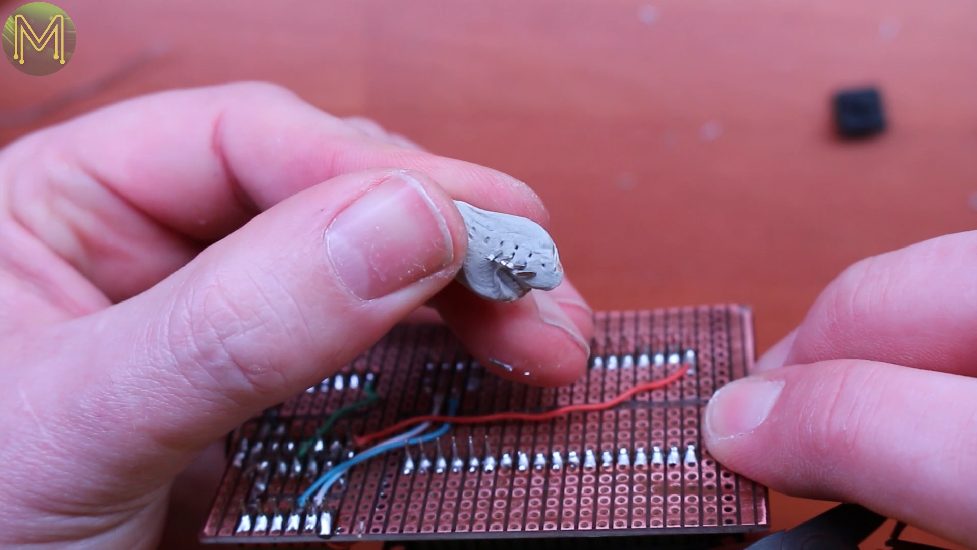
When cutting down the headers you can hold your finger over them to avoid them flying around the room. This can be a little painful. So you can also get some Blue-Tak, which will not only stop your finger being pierced, but stop them flying.

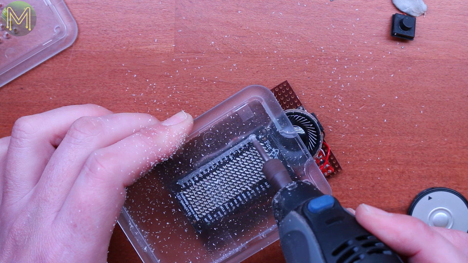

Now to check if it all fits in, but it seems it’s just a fraction too big caused by the LED display header pins. So I marked out where the header pins where located and dremmelled out the case so the pins would fit. Yup, that’s all that was needed.


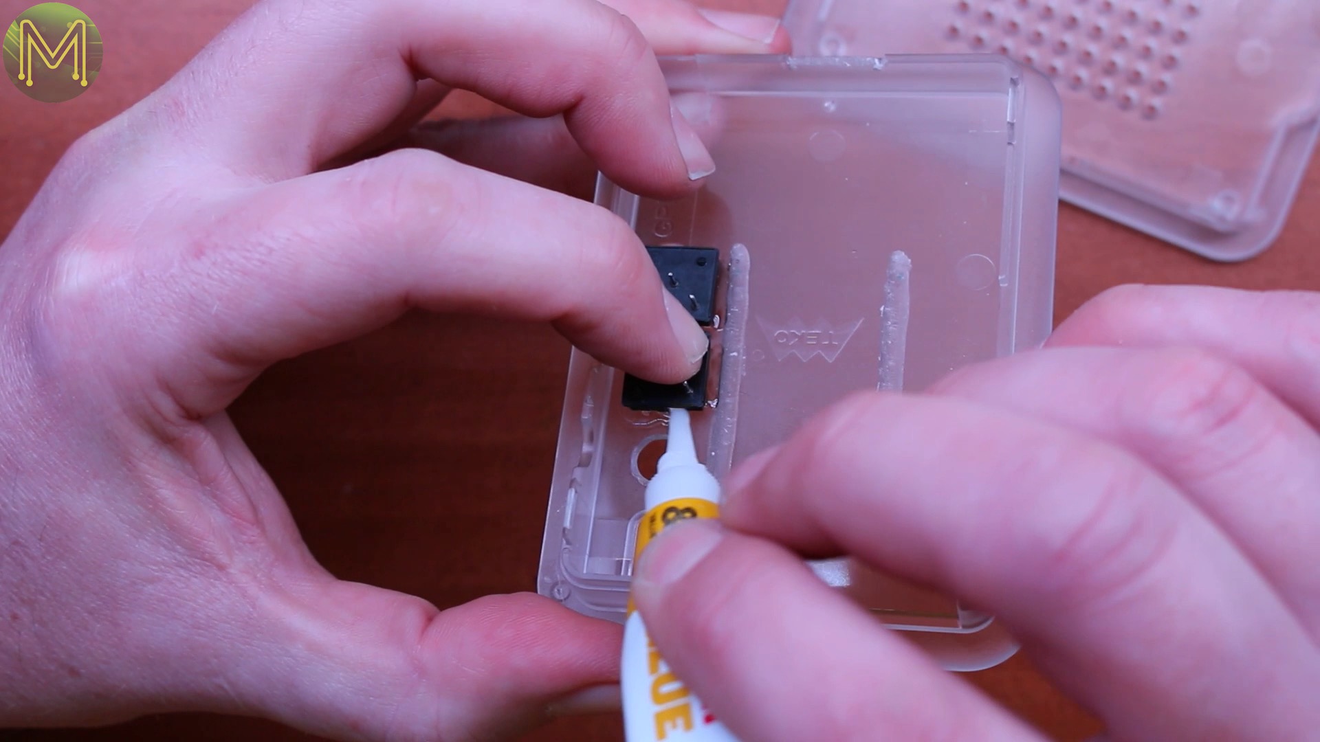
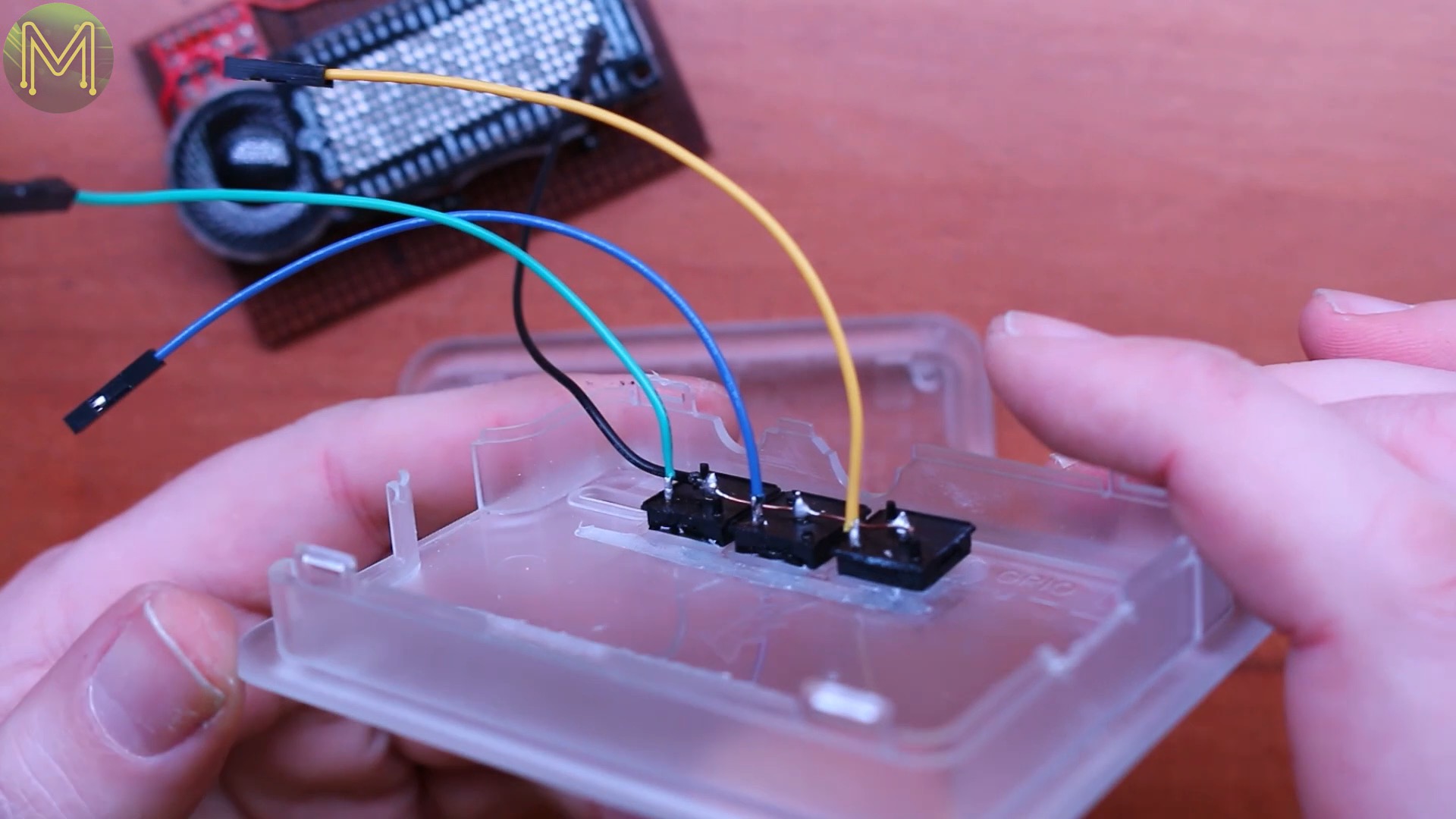
Next on to some buttons. I picked these up from some useless junk as well and drilled out three holes for them to fit. Then secured them with super glue. Noticed I glued just the sides. This was to avoid super glue getting into the button and stopping it from working. Next I soldered up a header for the three buttons and used some old hookup wire to solder up each of the buttons with a common ground wire.
Next on to the LDR. This was setup as a plain voltage divider and allowed the ESP32 to easily discover how much ambient light was around so it could auto-dim the display.
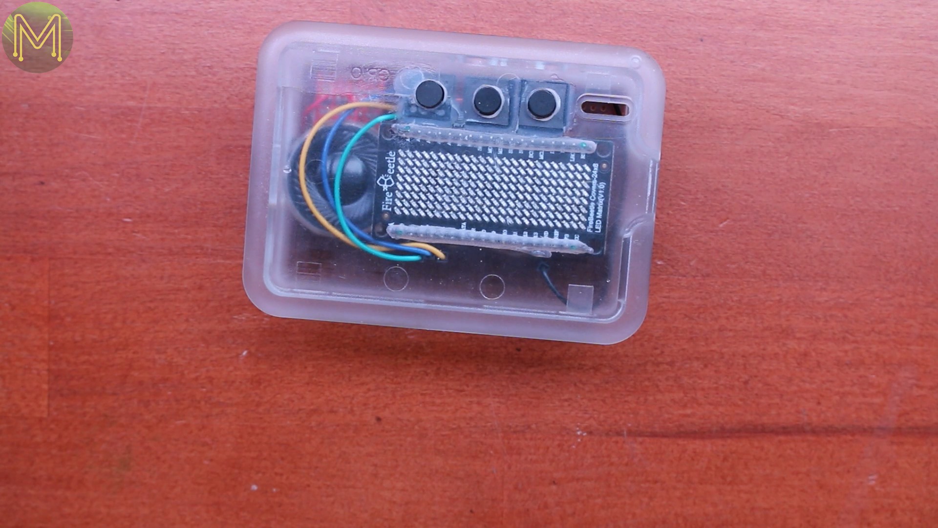
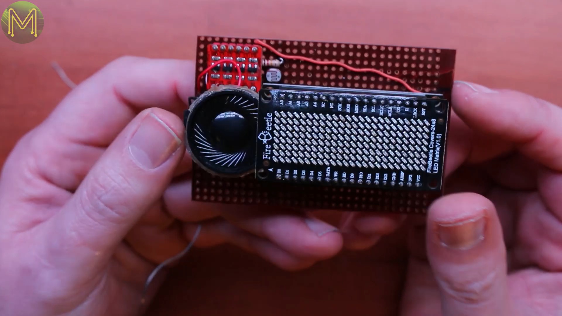
and there you have it. A nice little package!
Google calendars

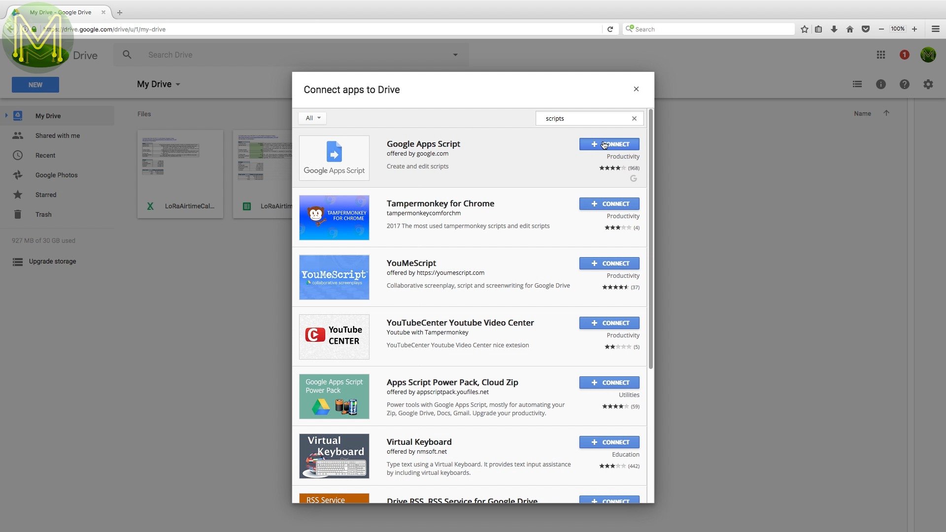
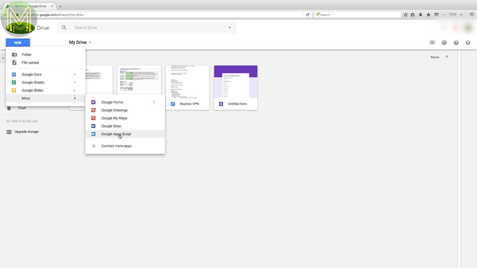
Next on to the Google calendar side. First you’ll need to login to Google Drive. Click on New, then “Connect more apps”, search for “scripts”, and connect that to your Google Drive account. Then click on “New” again, then “Google Apps Script”. This will open up a blank project.
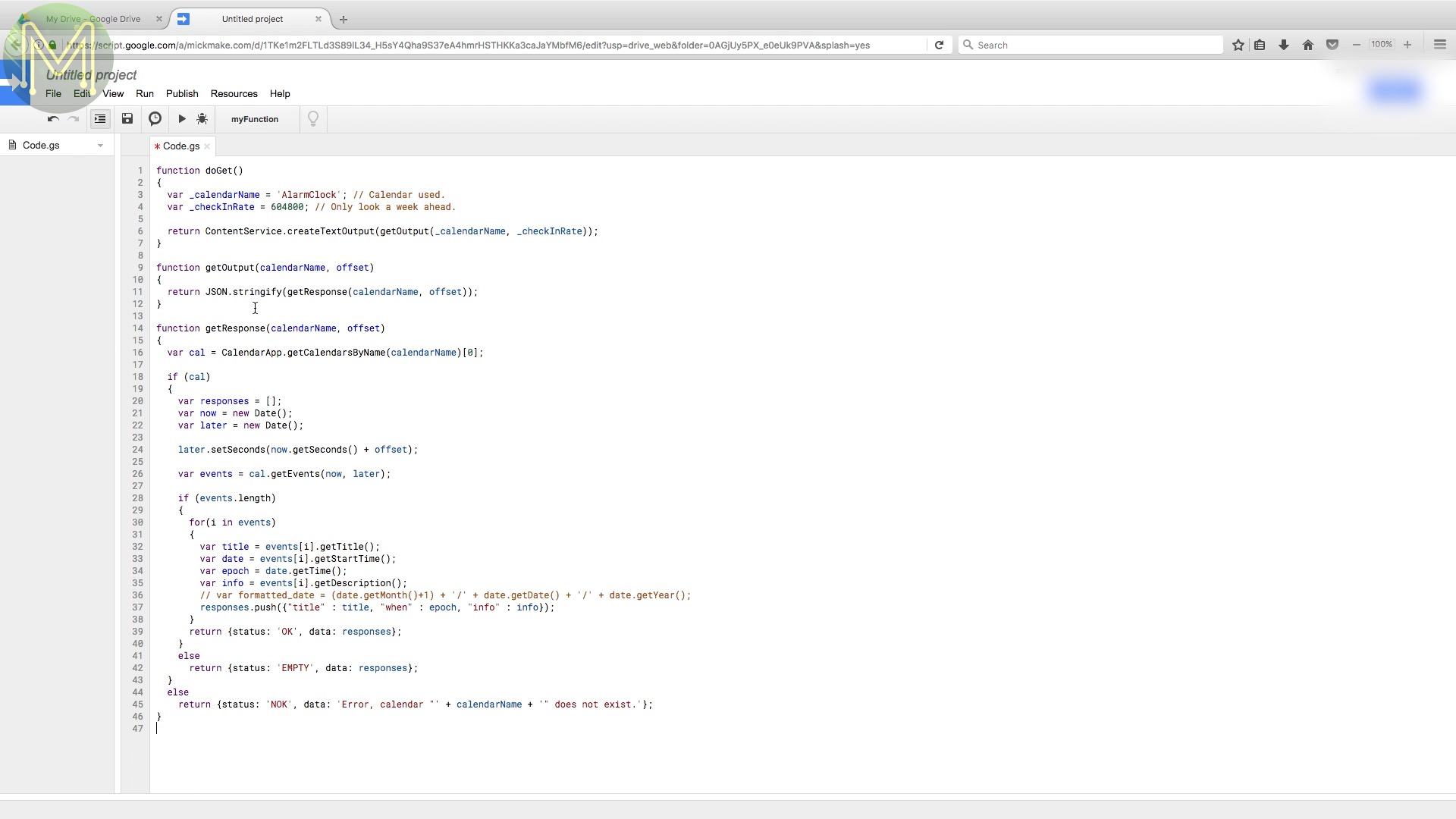
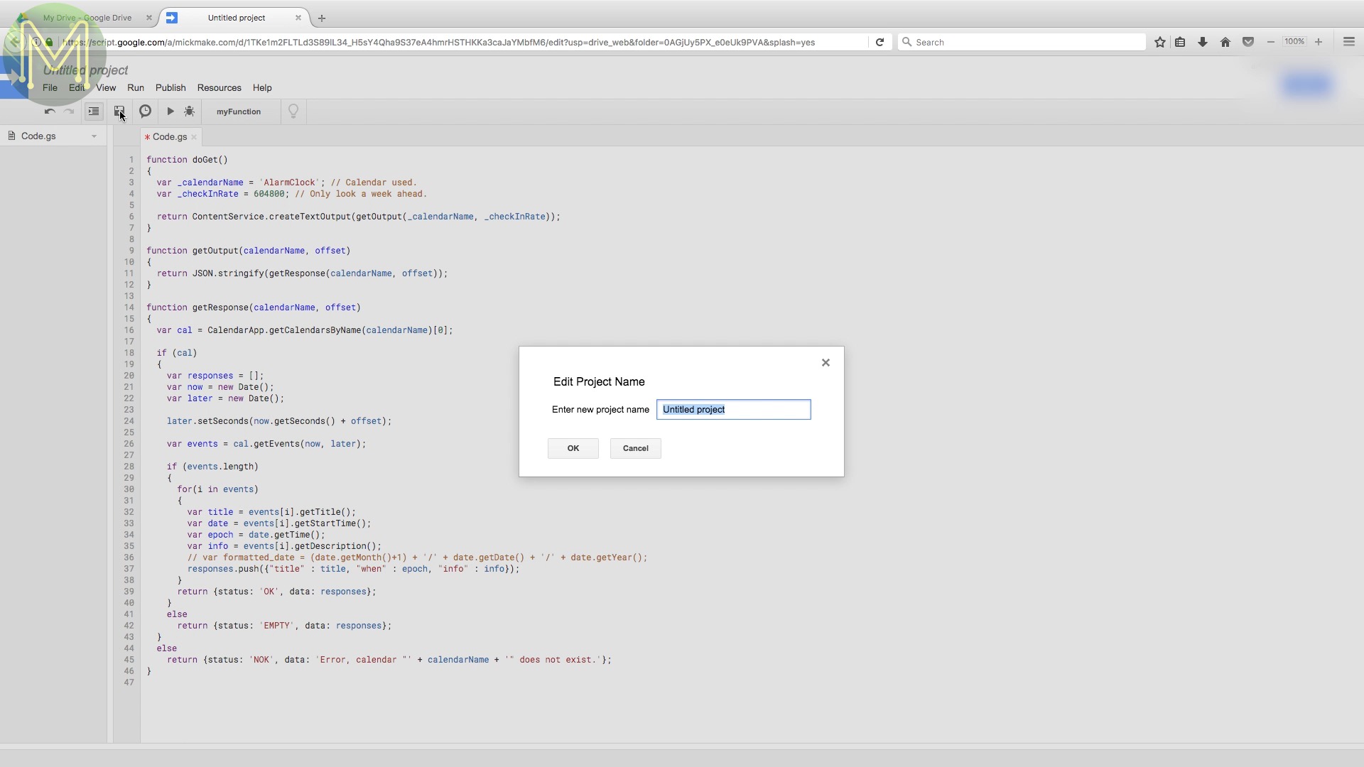

You will need to fetch the Google Script from my GitHub page and then paste it in here. Save it as anything you want. The name doesn’t matter. Then you’ll want to publish the script, select “Deploy as web app”.
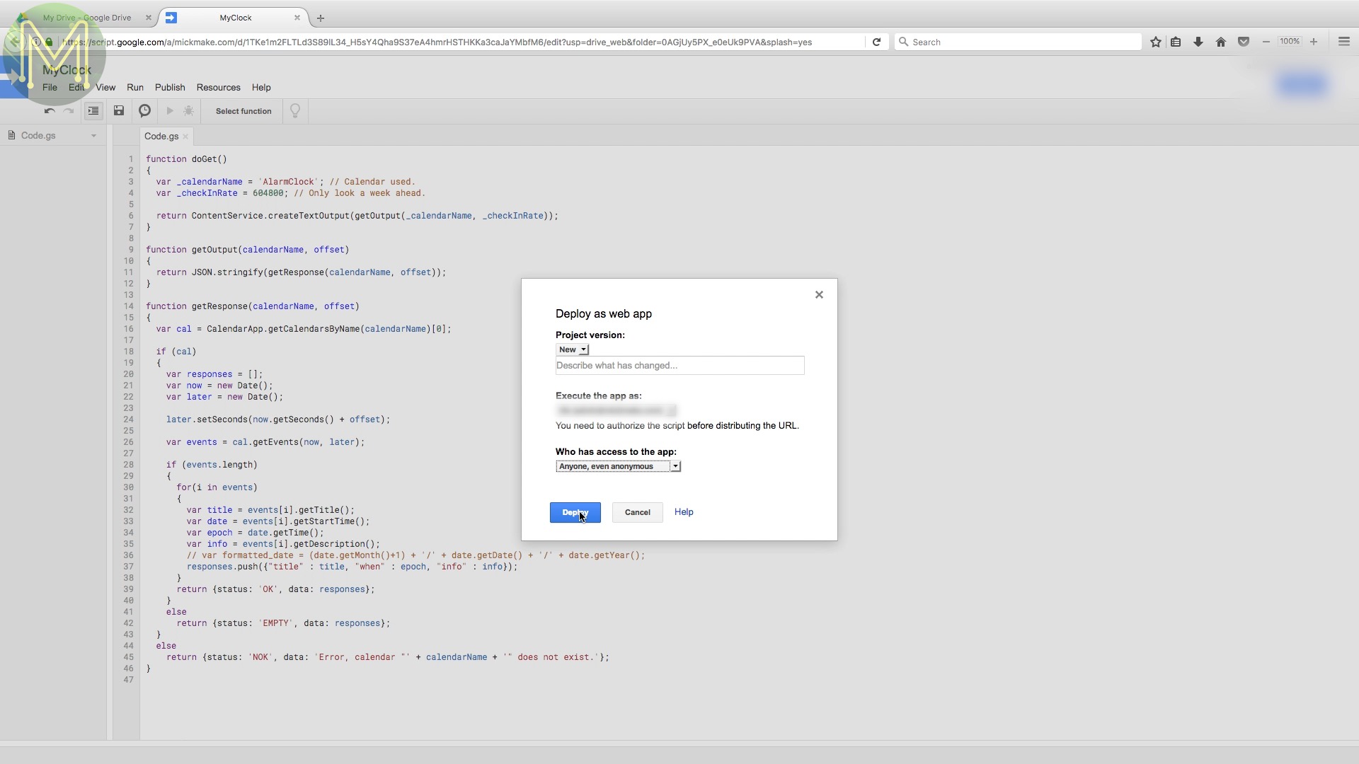
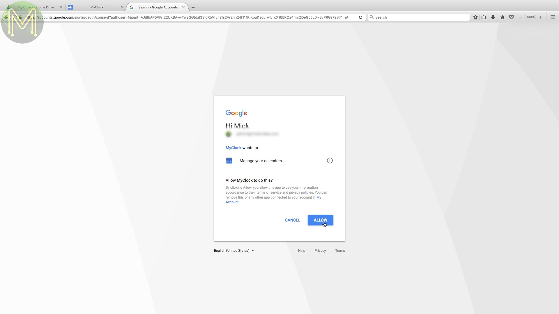
It’ll then ask you who has access to this app. Select anyone. You might be concerned about the security of this, but you’ll see why this isn’t an issue later. This will ask you to review your permissions. All it needs is access to your calendars. Click on “Allow” and here we find the reason why I said security isn’t an issue.
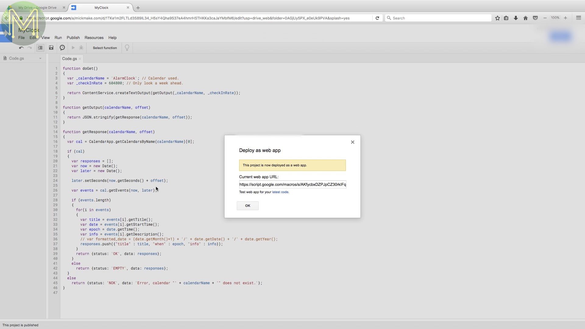
To access this script, you’ll need a very long URL, which sort of acts as a password anyway. So, I don’t think it’s an issue. In a later revision of this project I’ll add login security as well. Make sure you record this URL as you’ll need it later.

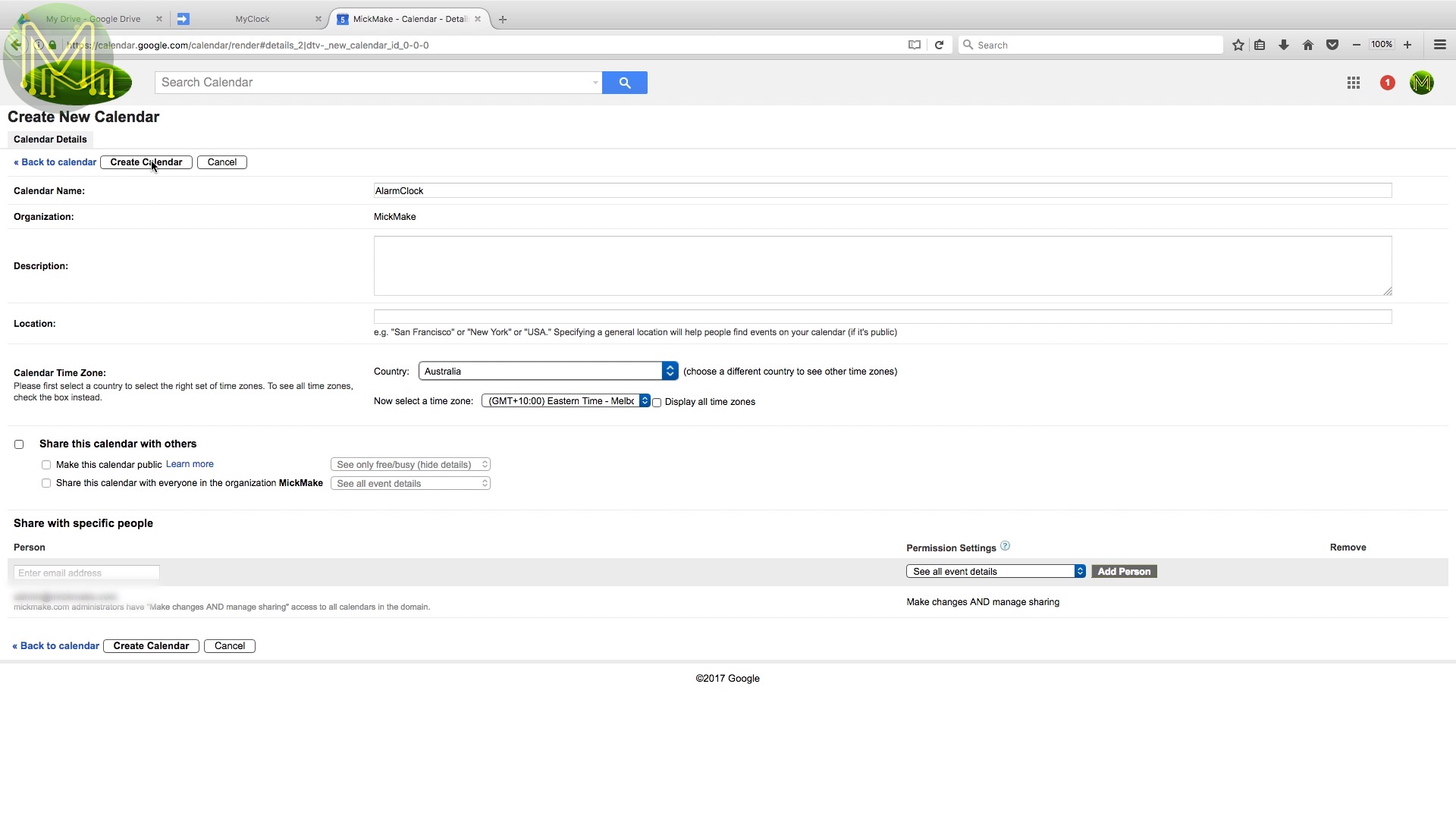

Next open up a calendar, then My calendars drop down and “Create new calendar”. You can use any name you want, but once again you’ll need to record this for later. Now you can create events in this calendar and your alarm clock will go off for every event you create.
Arduino IDE
/*
* Common defines that you'll need to update.
*
*/

/* Google calendar */
#define GCALURL "https://script.google.com/macros/s/SOME-RANDOM-LONG-STRING/exec"


/* WiFi network defines */
// Your WiFi SSID name
#define WIFI_SSID "Your WIFFY SSID";
// Your WiFi SSID password
#define WIFI_PASSWD "Your WIFFY passowrd";
// Your clock hostname
#define WIFI_HOSTNAME "Clock";


/* Web server defines */
// Web server port
#define WWW_PORT 80


/* NTP defines */
// NTP server to use
#define NTP_SERVER 10,0,0,12
// NTP port to listen on
#define NTP_PORT 123
// Time between NTP sync fetches
#define NTP_SYNC 60
// Default timezone to use
#define TIMEZONE 10 // Straya
//#define TIMEZONE -5; // Eastern Standard Time (USA)
//#define TIMEZONE -4; // Eastern Daylight Time (USA)
//#define TIMEZONE -8; // Pacific Standard Time (USA)
//#define TIMEZONE -7; // Pacific Daylight Time (USA)


/* MP3 player GPIO pins */
#define SERIAL2_RXPIN 16
#define SERIAL2_TXPIN 17
#define BUSY_PIN 4


/* Buttons & LDR GPIO pins */
#define BUTTON1 D2
#define BUTTON2 D3
#define BUTTON3 D4
#define LDR A0


/* FireBeetle 24x8 LED hat GPIO pins */
#if defined( ESP_PLATFORM ) || defined( ARDUINO_ARCH_FIREBEETLE8266 ) //FireBeetle-ESP32 FireBeetle-ESP8266
#define FBD_DATA D6
#define FBD_CS D5
#define FBD_WR D7
//#define FBD_RD D8
#else
#define FBD_DATA 6
#define FBD_CS 5
#define FBD_WR 7
//#define FBD_RD 8
#endif
Back in the Arduino IDE, make sure that you have entered in your WiFi SSID and password, and also the Google Script URL that you recorded. You can also update your timezone and NTP server in this file. If you’re every hacking with my code, there’s some useful debug defines you can use in the Debug.h header file.

Next you’ll need to load up an SD card with the MP3 files from my GitHub page. Make sure you place them in a folder called MP3. The alarm MP3 file should be placed in a folder called 01/.
enum enumMP3
{
 vfEmpty,
 vfSilence,
 vfTheTimeIs,
 vfTheDateIs,
 vfZero,
 vfOne,
 vfTwo,
 vfThree,
 vfFour,
 vfFive,
 vfSix,
 vfSeven,
 vfEight,
 vfNine,
 vfTen,
 vfEleven,
 vfTwelve,
 vfThirteen,
 vfFourteen,
 vfFifteen,
 vfSixteen,
 vfSeventeen,
 vfEighteen,
 vfNineteen,
 vfTwenty,
 vfThirty,
 vfFourty,
 vfFifty,
 vfOclock,
 vfOh,
 vfHundred,
 vfThousand,
 vfAnd,
 vfJanuary,
 vfFebruary,
 vfMarch,
 vfApril,
 vfMay,
 vfJune,
 vfJuly,
 vfAugust,
 vfSeptember,
 vfOctober,
 vfNovember,
 vfDecember,
 vfAM,
 vfPM
};
enumMP3 VF;
If you want to create your own then make sure that you record them in the order specified in the ClockMP3defs.h file. Keep the samples short. I used audacity to record myself saying each word one after the other with a half second gap between words. Then used the auto-silence detect of audacity to automatically remove silence. Then save each file in order. It was certainly a lot quicker than when I originally did it 30 years ago.
You will also need to fetch a couple of libraries. Most of these are in the Arduino IDE and you can simply search for them there and download and install.
Testing

Next plug it in. The clock will flash “NTP” until it gains a sync with whatever NTP server you set.Once synced it’ll display 24 hour time by default.
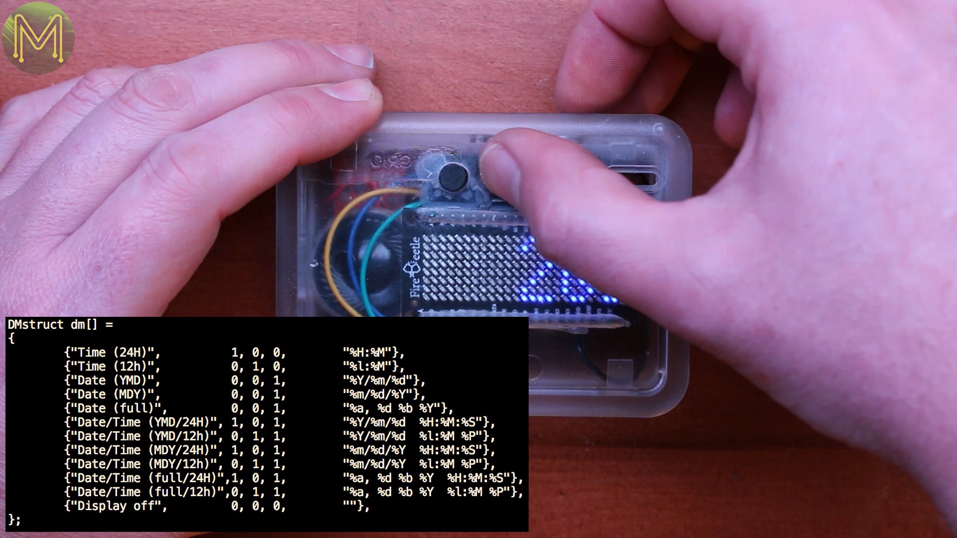
The middle button selects several different display modes. I use the C strftime function within a structure to display the time so you could update and change it to anything you want. This structure will also change what is said based on whether a date, time or both are being displayed.
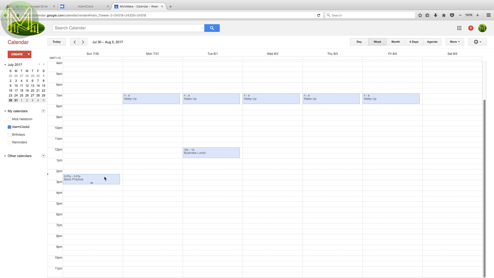
Go to Google calendar, set an arbitrary alarm point and there you go. The default alarm is a classic Beach boys song, what a way to wake up! Pressing any button will turn the alarm off and speak the time for you.

I mentioned a web interface before, well here it is. Pretty simple, but you have access to all the functins of the clock.
Summary
So there you have it, thirty years later and I have something that is miles better than the original.
I’ll be shortly making a PCB and 3D printed case for this project, so you can make your own and avoid all the messy soldering work. I’ll also be updating this project periodically and adding new features every so often - such as better security, multiple calendar syncing, louder amplified audio and the ability to change the MP3 file played from Google calendar.
So, check my HackADay project page for updates. If you make one yourself it’d be great to hear about it in the comments below.